BROCHURE — Hilge CONTRA
GEA.com
GEA HILGE CONTRA Single- and Multi-Stage Pumps Catalog
3
Legal notice Publication date: June 2026
The publication of specifications, technical data and information in written or electronic form does not release the user from the responsibility of checking for themselves all products delivered by us for suitability for the application(s) intended. These may be subject to change without prior notification. Errors and printing errors excepted – we assume no liability for the correctness of specifications given.
The general terms and conditions of delivery apply.
All rights reserved – copyright on all contents. The ® symbol in this catalog identifies a trademark registered in certain countries.
GEA Hilge Niederlassung der GEA Tuchenhagen GmbH Hilgestraße 37–47, 55294 Bodenheim, Germany
CONTENTS 06 Flow Components
06 Introduction
07 Hygienic Pumps
07 Introduction
18 Certificates
20 GEA Hilge CONTRA Pumps
20 Overview
28 Product Range
29 Connection Guide
32 Seals
33 ATO-Program
34 Installation
36 Media Guide
46 Pump Selection Matrix
48 Connection Dimensions – GEA Hilge CONTRA I
54 Connection Dimensions – GEA Hilge CONTRA II
58 Connection Dimensions – GEA Hilge CONTRA III
60 GEA Hilge CONTRA I
62 Pump Selection Matrix
64 GEA Hilge CONTRA I Bloc – on Motor Foot
65 GEA Hilge CONTRA I Bloc – on Combi Foot
66 GEA Hilge CONTRA I Bloc – on Cast Iron Foot
67 GEA Hilge CONTRA I Bloc – on Stainless Steel Foot
68 GEA Hilge CONTRA I Bloc-SUPER – on Combi Foot
69 GEA Hilge CONTRA I Bloc-SUPER – on Cast Iron Foot
70 GEA Hilge CONTRA I Bloc-SUPER – on Stainless Steel Foot
71 GEA Hilge CONTRA I Bloc-V – on Vertical Stand
72 GEA Hilge CONTRA I Adapta/Adapta-tronic – on Combi Foot (80–90)
73 GEA Hilge CONTRA I Adapta/Adapta-tronic – on Combi Foot (100–132)
74 GEA Hilge CONTRA I Adapta/Adapta-tronic – on Cast Iron Foot
75 GEA Hilge CONTRA I Adapta/Adapta-tronic – on Stainless Steel Foot
76 GEA Hilge CONTRA I Adapta-SUPER – on Combi Foot (80–90)
77 GEA Hilge CONTRA I Adapta-SUPER – on Combi Foot (100–132)
78 GEA Hilge CONTRA I Adapta-SUPER – on Cast Iron Foot
79 GEA Hilge CONTRA I Adapta-SUPER – on Stainless Steel Foot
80 GEA Hilge CONTRA I Adapta/Adapta-tronic – on Vertical Stand
82 Performance Curves
82 GEA Hilge CONTRA I – 1-stage, 50 Hz
83 GEA Hilge CONTRA I – 2-stage, 50 Hz
84 GEA Hilge CONTRA I – 3-stage, 50 Hz
85 GEA Hilge CONTRA I – 4-stage, 50 Hz
86 GEA Hilge CONTRA I – 5-stage, 50 Hz
87 GEA Hilge CONTRA I – 6-stage, 50 Hz
88 GEA Hilge CONTRA I – 1-stage, 60 Hz
89 GEA Hilge CONTRA I – 2-stage, 60 Hz
90 GEA Hilge CONTRA I – 3-stage, 60 Hz
91 GEA Hilge CONTRA I – 4-stage, 60 Hz
5
92 GEA Hilge CONTRA II
94 Pump Selection Matrix
96 GEA Hilge CONTRA II Bloc – on Motor Foot
97 GEA Hilge CONTRA II Bloc – on Combi Foot (90–132)
98 GEA Hilge CONTRA II Bloc – on Combi Foot (160)
99 GEA Hilge CONTRA II Bloc – on Cast Iron Foot
100 GEA Hilge CONTRA II Bloc – on Stainless Steel Foot
101 GEA Hilge CONTRA II Bloc-SUPER – on Combi Foot (90–132)
102 GEA Hilge CONTRA II Bloc-SUPER – on Combi Foot (160)
103 GEA Hilge CONTRA II Bloc-SUPER – on Cast Iron Foot
104 GEA Hilge CONTRA II Bloc-SUPER – on Stainless Steel Foot
105 GEA Hilge CONTRA II Bloc-V – on Vertical Stand
106 GEA Hilge CONTRA II Adapta/Adapta-tronic – on Combi Foot
107 GEA Hilge CONTRA II Adapta/Adapta-tronic – on Adjustable Feet (160)
108 GEA Hilge CONTRA II Adapta/Adapta-tronic – on Adjustable Feet (180)
109 GEA Hilge CONTRA II Adapta/Adapta-tronic – on Cast Iron Foot
110 GEA Hilge CONTRA II Adapta/Adapta-tronic – on Stainless Steel Foot
111 GEA Hilge CONTRA II Adapta/Adapta-tronic – on Adapta Foot
112 GEA Hilge CONTRA II Adapta-SUPER – on Combi Foot
113 GEA Hilge CONTRA II Adapta-SUPER – on Adjustable Feet (160)
114 GEA Hilge CONTRA II Adapta-SUPER – on Adjustable Feet (180)
115 GEA Hilge CONTRA II Adapta-SUPER – on Cast Iron Foot
116 GEA Hilge CONTRA II Adapta-SUPER – on Stainless Steel Foot
117 GEA Hilge CONTRA II Adapta/Adapta-tronic – on Vertical Stand
118 Performance Curves
118 GEA Hilge CONTRA II – 2-stage, 50 Hz
119 GEA Hilge CONTRA II – 3-stage, 50 Hz
120 GEA Hilge CONTRA II – 4-stage, 50 Hz
121 GEA Hilge CONTRA II – 5-stage, 50 Hz
122 GEA Hilge CONTRA II – 2-stage, 60 Hz
123 GEA Hilge CONTRA II – 3-stage, 60 Hz
124 GEA Hilge CONTRA II – 4-stage, 60 Hz
125 GEA Hilge CONTRA II – 5-stage, 60 Hz
126 GEA Hilge CONTRA III
128 Pump Selection Matrix
130 GEA Hilge CONTRA III Adapta – on Vertical Stand
131 Performance Curves
131 GEA Hilge CONTRA III – 2-stage, 50 Hz
132 GEA Hilge CONTRA III – 3-stage, 50 Hz
133 GEA Hilge CONTRA III – 4-stage, 50 Hz
134 GEA Hilge CONTRA III – 2-stage, 60 Hz
135 GEA Hilge CONTRA III – 3-stage, 60 Hz
136 Appendix
136 Inquiry Sheet
138 Description of Certificates and Test Reports
139 Abbreviations and Terms
Flow Components
ALwAyS IN mOTION wITH fLOw COmpONENTS
GEA Flow Components The Flow Components Portfolio comprises hygienic pumps, valve technology and cleaning technology. Our products comply with the highest hygiene standards, such as EHEDG and 3-A. Our customers’ success depends on the quality and profitability of their products. That is why they rely on advanced technology and on our decades of experience in ensuring smooth processing of liquid products. Our sophisti- cated process components and service offers for everything that flows are available worldwide from the international GEA sales network.
“Regardless of the application – for our customers product quality and profitability are what matters. This is what GEA Flow Components is known for. Our engineers are specialists in everything that flows.”
Around one quarter of the milk processed is handled by GEA equipment
Roughly every second liter of beer is brewed using GEA equipment and solutions
Every fourth liter of human blood is handled by GEA equipment
Approx. one in three instant coffee lines has been built by GEA
6
Hygienic Pumps
GEA Hilge Hygienic Pumps – The heart of every process GEA Hilge offers a versatile range of centrifugal and positive displacement pumps for a wide variety of sensitive applica- tions in the beverage, food and pharmaceutical industries.
Our pumps with their sophisticated design ensure particularly gentle conveyance of the respective medium, offer lasting reli- ability and are characterized by economic efficiency. After all, hygienic pumps are used in processes that directly affect the product and production. They are the heart of every process.
State-of-the-art pump technology, made to our customers’ preferences At the GEA Hygienc Pumps Competence Center we develop innovative pumps and processes together with our customers. Our decades of up-close experience with operations and systems at our customers’ production sites ensure optimum selection and configuration of the right pumps for every application.
Maximum efficiency Two product lines, GEA VARIPUMP and GEA SMARTPUMP, enable our customers to choose from a highly versatile pump range with a multitude of smart adaption options to achieve simpler operation, higher-quality production, and reduced consumption of valuable resources. Special construction fea- tures of our many types of pumps provide for exceptionally gentle product handling, delivering top-quality products to consumers.
Maximum reliability Our customers rely on the safe, continuous operation of their production processes without unplanned breaks or disturbances. That is why GEA pumps are optimized for uncompromising reli- ability in all applications. Thanks to their robust design and long service life, they are known as “workhorses” for their ease of maintenance and outstanding service, proven over decades, and for the great number of pumps currently in operation. Of course, GEA pumps also comply with all relevant hygiene stan- dards and norms with continuous documentation and up-to-date certifications safely ensuring judicial security.
Hygienic Pumps
7
8 Hygienic Pumps | Introduction
Two modern pump lines for maximum efficiency Two product lines, GEA Varipump and GEA Smartpump, form a highly versatile pump range with a multitude of adaption options to ensure simpler operation, higher-quality produc- tion, and reduced consumption of valuable resources.
Selecting and configuring the right pump requires a high level of experience. The selection matrix provides initial guidance.
Hygienic Pumps Introduction
Complex applications with advanced requirements
High system pressures, high media temperatures, high solid content in media,
highest requirements regarding surface quality and materials
Standard applications with low complexity
System pressures up to 16 bar, low media temperatures,
non-critical conveying media, standard requirements regarding surface quality and materials
GEA Smartpump
GEA Varipump
C om pl ex ity o f c us to m er a pp lic at io n
Degree of user-specific adjustment
Standard pump types Pre-defined model variants for common applications
High flexibility Individual adjustment, custom engineering
9Hygienic Pumps | Introduction
GEA Varipump The pump series in the GEA Varipump line have been conceived for extreme application demands. The pumps are individually optimized by GEA for each task.
GEA Varipump models are made entirely without die-cast components, offering high-quality surfaces and materials that meet stringent demands even in the sensitive pharmaceutical industry, further ensured by complementing services, e.g. Witnessed Factory Acceptance Test (FAT).
With a great variety of set-up and customizing options the pumps can be adapted individually to any production process, for lower operational costs and maximum system efficiency.
• Developed for advanced application conditions • Project-specific customization • Surface roughness up to Ra ≤ 0.4 µm (not applicable for GEA Hilge MAXA)
• Selection of materials in contact with product according to specific requirements (e.g. no cast parts, Fe ≤ 1 % optional)
GEA Smartpump The GEA Smartpump line comprises highly standardized and attractively priced pump series for common, often-used appli- cations at standard conditions. The pumps are easy to select and ready for fast delivery. Within pre-defined parameters, the standard models can be configured to individual tasks.
The modular construction using high-value materials, the proven “Hygienic Design” and easy-to-apply standardized spare parts all recommend GEA Smartpump pumps for use in cost-critical production systems – at no compromise in terms of quality.
• Application for common and clearly defined “standard” process tasks
• Simple selection and configuration • Fast delivery • Standardized spare parts • Surface roughness up to Ra ≤ 0.8 μm (not applicable for GEA Hilge DURIETTA)
SIPLA
TPS
TPS
SIPLA
0 200100 300 500400 450
200
150
250
100
50
300
350
600 140
80
40
20
60
100
120
Q [US gpm]
Q [m3/h] 1400 40 80 12020 60 100
00
H [m][ft]
400
Q [m3/h] 1400 40 80 12020 60 100
0 200100 300 500400 600 Q [US gpm]
450
200
150
250
100
50
300
350
140
80
40
20
60
100
120
00
H [m][ft]
400
Self-priming Pumps, 50 Hz
Self-priming Pumps, 60 Hz
Hygienic Pumps | Introduction | Performance Curves
Hygienic Pumps Introduction Performance Curves
10
SIPLA
TPS
TPS
SIPLA
0 200100 300 500400 450
200
150
250
100
50
300
350
600 140
80
40
20
60
100
120
Q [US gpm]
Q [m3/h] 1400 40 80 12020 60 100
00
H [m][ft]
400
Q [m3/h] 1400 40 80 12020 60 100
0 200100 300 500400 600 Q [US gpm]
450
200
150
250
100
50
300
350
140
80
40
20
60
100
120
00
H [m][ft]
400
Self-priming Pumps, 50 Hz
Self-priming Pumps, 60 Hz
MAXAHYGIA
TP
CONTRA
DU RI
ET TA
TP
DU RI
ET TA
CONTRA
HYGIA MAXA
Q [US gpm] 0 200 400 600 800 1000 1200
Q [US gpm]
H [m][ft] 240
160
80
120
40
400
300
500
200
100
600
700
0 0 3200 80 160 24040 120 200 280
200
H [m][ft] 240
160
80
120
40
400
300
500
200
100
600
700
0 0
200
0 200 400 600 800 1000 1200
Q [m3/h] 3200 80 160 24040 120 200 280
Q [m3/h]
Centrifugal Pumps, 2-pole, 50 Hz
Centrifugal Pumps, 2-pole, 60 Hz
Hygienic Pumps | Introduction | Performance Curves 11
MAXA, 4-pole
TP, 4-pole
MAXA, 6-pole
HYGIA, 4-pole
HYGIA, 4-pole
Q [US gpm]
Q [m3/h] 0 200 400 1000100 300 500 16001400
H [m][ft]
0 0
60
100
40
20
80
200
100
150
50
300
250
0 500 1000 1500 2500 4500
600 800
35002000 6000
Q [US gpm]
Q [m3/h] 0 200 400 1000100 300 500 16001400
H [m][ft]
0 0
60
100
40
20
80
200
100
150
50
300
250
0 500 1000 1500 2500 4500
600 800
35002000 6000
Centrifugal Pumps, 4-/6-pole, 50 Hz
Centrifugal Pumps, 4-/6-pole, 60 Hz
MAXA, 4-pole
MAXA, 6-pole
TP, 4-pole
Hygienic Pumps | Introduction | Performance Curves
Hygienic Pumps Introduction Performance Curves
12
13
HYGIA H II
HYGIA H III
HYGIA H III
HYGIA H II
HYGIA H I
HYGIA H I
High-pressure Pumps, 60 Hz
H [m][ft] 160
150
80
40
20
60
100
110
120
130
140
70
30
10
50
90
0
550
200
150
250
100
50
300
350
400
450
500
0
0 200100 700 800300 500400 600 900 Q [US gpm]
Q [m3/h] 2200 40 80 120 18020 60 100 140 200160
H [m][ft] 160
150
80
40
20
60
100
110
120
130
140
70
30
10
50
90
0
550
200
150
250
100
50
300
350
400
450
500
0
0 200100 700 800300 500400 600 900 Q [US gpm]
Q [m3/h] 2200 40 80 120 18020 60 100 140 200160
High-pressure Pumps, 50 Hz
MAXA, 4-pole
TP, 4-pole
MAXA, 6-pole
HYGIA, 4-pole
HYGIA, 4-pole
Q [US gpm]
Q [m3/h] 0 200 400 1000100 300 500 16001400
H [m][ft]
0 0
60
100
40
20
80
200
100
150
50
300
250
0 500 1000 1500 2500 4500
600 800
35002000 6000
Q [US gpm]
Q [m3/h] 0 200 400 1000100 300 500 16001400
H [m][ft]
0 0
60
100
40
20
80
200
100
150
50
300
250
0 500 1000 1500 2500 4500
600 800
35002000 6000
Centrifugal Pumps, 4-/6-pole, 50 Hz
Centrifugal Pumps, 4-/6-pole, 60 Hz
MAXA, 4-pole
MAXA, 6-pole
TP, 4-pole
Hygienic Pumps | Introduction | Performance Curves
NOVALOBE 60
NOVALOBE 50
NOVALOBE 40
NOVALOBE 30
NOVALOBE 20
NOVALOBE 10
Q [m3/h][US gpm]
100
1
15
315
0 1 10 100 1000 10000
30
10
20
300
100000
45
60
5
45
130
70
200
[mPas]η
Rotary Lobe Pumps
Hygienic Pumps | Introduction | Performance Curves
Hygienic Pumps Introduction Performance Curves
NOVATWIN+ 45
NOVATWIN+ 40
NOVATWIN+ 35
NOVATWIN+ 30
NOVATWIN+ 20
NOVATWIN+ 10
NOVATWIN+ 25
Q [m3/h][US gpm]
300
0
200
50200
0 1 10 100 1000 10000
250
150
400
1200
100000
100
600
1000
800
[mPas]η
Twin Screw Pumps
14
NOVALOBE 60
NOVALOBE 50
NOVALOBE 40
NOVALOBE 30
NOVALOBE 20
NOVALOBE 10
Q [m3/h][US gpm]
100
1
15
315
0 1 10 100 1000 10000
30
10
20
300
100000
45
60
5
45
130
70
200
[mPas]η
Rotary Lobe Pumps
Hygienic Pumps | Overview
Hygienic Pumps Overview
GEA Hilge HYGIA / HYGIA H The “Swiss Knife” among the hygienic pumps. Premium quality, reliability and highest flexibility of customization ensure successful application in the food, beverage, and pharma industries. Also avail- able as high-pressure execution.
GEA Hilge TP The GEA Hilge TP is the smart solution for standard applications. The single-stage centrifugal pump suits a wide range of applications and offers uncompromising hygiene and quality.
GEA Hilge MAXA A single-stage centrifugal pump designed for heavy-duty operation in industrial processes. Especially used in fermentation broth, filtration facilities and transportation of condensate, hot and cold water.
Single-stage end-suction centrifugal pumps
GEA VARIPUMP Wide model range with numerous variants. Customization to specific customer requirements
GEA SMARTPUMP Clearly defined list of models, limited to standard requirements, no other variants
GEA Hilge HYGIA
GEA Hilge TP
GEA Hilge MAXA
Technical data 50 Hz 60 Hz
Max. flow rate 200 m3/h 175 m3/h
Max. head 100 m 145 m System pressure 16 / 25 / 64 bar
Technical data 50 Hz 60 Hz
Max. flow rate 1,450 m3/h 1,320 m3/h
Max. head 100 m 100 m System pressure 10 bar 10 bar
Technical data 50 Hz 60 Hz
Max. flow rate 215 m3/h 245 m3/h
Max. head 90 m 130 m System pressure* 16 bar 16 bar
* GEA Hilge TP 1020 10 bar
16
17Hygienic Pumps | Overview
GEA Hilge TPS This self-priming centrifugal pump is the solution of choice especially for emptying tanks as well as for conveying products containing gas, e.g. CIP return systems.
GEA Hilge SIPLA A single-stage self-priming side channel pump, especially suited for SIP/CIP return systems and applications with high gas content. Right- and left-hand rotation can be freely adjusted for additional application options.
GEA Hilge DURIETTA This end-suction single- or multi- stage centrifugal pump in a very compact design has been created for applications with low flow rates at high flow heads.
GEA Hilge CONTRA Single- and multi-stage centrifugal pumps are available in this series. The hygienic design in every detail provides perfect solutions to numerous tasks in sterile and hygienic processes.
GEA Hilge NOVALOBE This rotary lobe pump has been specifically designed for highly viscous media – and for applica- tions where gentle pumping is required. The pump is fully drain- able with vertical ports.
GEA Hilge NOVATWIN+ The flexible 3-A certified twin screw pump range allows production and CIP operation with one pump. It fulfills the highest hygienic requirements and ensures reliable production.
Single-stage self-priming centrifugal pumps
Multi-stage centrifugal pumps
GEA Hilge SIPLA
GEA Hilge TPS
GEA Hilge CONTRA
GEA Hilge DURIETTA
GEA Hilge NOVALOBE GEA Hilge NOVATWIN+
Rotary lobe pumps
Positive displacement pumps
Twin-screw pumps
Technical data 50 Hz 60 Hz
Max. flow rate 78 m3/h 64 m3/h
Max. head 47 m 60 m System pressure 10 bar 10 bar
Technical data 50 Hz 60 Hz
Max. flow rate 100 m3/h 100 m3/h
Max. head 200 m 230 m System pressure 25 bar 25 bar
Technical data 50 / 60 Hz
Max. displacement 2.1 l/rev Max. differential pressure 16 bar
System pressure 10/16 bar
Technical data 50 / 60 Hz
Max. flow rate 310 m3/h Max. differential pressure 25 bar
System pressure up to 30 bar
Technical data 50 Hz 60 Hz
Max. flow rate 115 m3/h 125 m3/h
Max. head 95 m 138 m System pressure 16 bar 16 bar
Technical data 50 Hz 60 Hz
Max. flow rate 8 m3/h 8 m3/h
Max. head 72 m 41 m System pressure 8 bar 8 bar
18 Hygienic Pumps | Certificates
Hygienic Pumps Certificates
The certificates listed here are valid for corresponding GEA pump models. Pumps conforming to the requirements of the European Hygienic Engineering and Design Group (EHEDG) as well as 3-A Sanitary Standards, Inc. (3-A SSI) are available for numerous fields of application.
EHEDG certificates apply only to the specific pump type as listed. However, they may be transferred to specific other pump types, owing to identical housing designs and flow path geometries.
Pump
G EA H ilg e
H YG IA /
H YG IA H
G EA H ilg e
TP / TP S
G EA H ilg e
C O N TR A
G EA H ilg e
M A X A
G EA H ilg e
D U RI ET TA
G EA H ilg e
SI PL A
G EA H ilg e
N O VA LO BE
G EA H ilg e
N O VA TW IN +
Document 3-A Sanitary Standard • • • • EHEDG certificate •* •* •* • •*
FDA declaration of conformity • • • • • • • • Declaration of compliance with the order 2.1 acc. to EN 10204 • • • • • • • • Test report 2.2 acc. to EN 10204 • • • • • • • • Inspection certificate 3.1 acc. to EN 10204 • • • • • • • EAC-Certificate •* • • • • • • • Surface roughness test report • • • • • • Delta ferrite test report • • • • Acoustic measurement test report • • • • • • • • USP Class VI – declaration of conformity • • • • • • Certificate in acc. with the regulation (EG) No. 1935/2004 • • • • • • • • Certificate DIN EN ISO 9001:2015 • • • • • • • • Many more certificates on request Subject to change without notice. * registered for certification / recertification
Moreover, independent, standardized tests have confirmed the efficient, problem-free cleaning ability of numerous pumps – for optimum safety and economic gain.
20 GEA Hilge TP Pumps | Overview
Features and benefits • �Process safety, reliability, and optimal cleanability, due to sterile, cast-free stainless steel, deep-drawn or forged without blowholes (Hygienic Design).
• �When installed vertically, the pump is completetly self-draining without a drain valve.
• �Ideally adaptable to customer needs and demanding tasks thanks to variable connections, seals and mountings.
• �Precise sizing for optimum efficiency and matching of duty point thanks to selectable impeller geometries. Additional flexibility through operation on a frequency converter.
• �Great flow and pressure control thanks to the steep performance curve.
Overview • �Gentle handling of shear-sensitive media thanks to very low NPSH values, minimizing cavitation and wear.
• �The Adapta version enables quick and easy motor change, the pump can remain in the pipeline (requires no revalidation in pharmaceutical applications).
• �Facilitated system qualification due to extensive customerand requirement-specific documentation and certificates.
• �One sealing concept for the entire centrifugal pump portfolio (single-stage, multi-stage, self-priming pumps) minimizes wearing parts logistics.
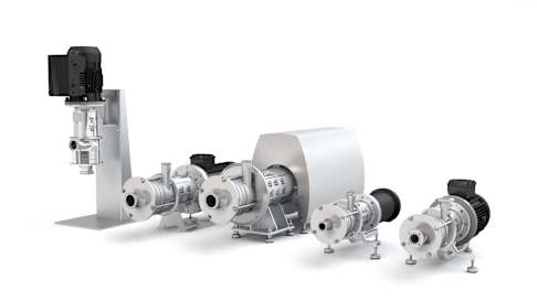
We’re Family GEA Hilge CONTRA product range
21GEA Hilge CONTRA Pumps | Overview
Technical Data
Applications The GEA Hilge CONTRA pump range is suitable for the following application areas and products, due to the hygienic design and material selection:
�Food and beverage industry • Breweries (beer, wort, mash, yeast, etc.) • �Dairies (milk, milk-based mixed beverages, cheese manufacturing, etc.)
• Soft drinks (fruit juice, lemonade, mineral water, etc.) • Wine and champagne cellars • Distilleries (mash, distillates, etc.) • Food manufacturing (marinades, brine, cooking oil, etc.) • Cleaning In Place systems (CIP)
Pharmaceutical and biotechnology • Pure-water systems (WFI) • Infusion • Culture medium • Blood plasma • Lotions • Perfumes
GEA Hilge CONTRA I
GEA Hilge CONTRA II
GEA Hilge CONTRA III
50 Hz 60 Hz 50 Hz 60 Hz 50 Hz 60 Hz
Flow rate 12 m3/h 15 m3/h 40 m3/h 35 m3/h 100 m3/h Head 100 m 100 m 160 m 230 m 230 m 215 m System pressure up to 25 bar Operating temperature 95 °C
Sterilization temperature 150 °C (SIP)
Max. pump efficiency 62 %
Pump connections GEA Hilge offers the following standard connections for the GEA Hilge CONTRA pump range: • Thread according to DIN 11851 • Flanges according to DIN 11864-2
You can find additional information in the connection selection guide on page 29.
The pumps are available in two sizes with a variety of flexible versions. The pumps are CIP- and SIP-capable in compliance with the DIN EN 12462 performance criteria. The design fulfills the following requirements: • EHEDG (registered for recertification) • EAC • GMP regulations
Design GEA Hilge CONTRA pumps are single- and multi-stage, end- suction centrifugal pumps, designed to meet the hygienic requirements of sterile process technology.
The pump casing is made of heavy-duty, rolled and deep-drawn and forged CrNiMo steel 1.4404 / 1.4435, the equivalent of AISI 316L. The GEA Hilge CONTRA pumps are equipped with open diffusor casings. The O-ring seal loctions for the casing and impellers meet hygienic design criteria. The vertical versions of GEA Hilge CONTRA pumps are fully self-draining through the suction port.
Certification
ATEX For use in potentially explosive areas, Adapta pumps are available. These pumps, which possess an EC declaration of conformity in accordance with the ATEX guideline 2014/34/ EU, correspond to device categories 2 or 3, and can be used in zone 1 or 2.
ATEX-Symbol
The special groove ensures that the seal is kept reliably in place at all times. The metallic stop allows a defined compression of the seal, ensuring gap-free sealing against the product cham- ber without dead legs. The pumps have a mechanical seal and a fan-cooled asynchronous motor to enclosure class IP55.
22 GEA Hilge CONTRA Pumps | Overview
Semi-open impeller The electro-polished, stainless steel, semi-open impeller is available in two versions, according to the application. The impeller is suitable for low-viscosity liquids and liquids con- taining low content of particles.
Impeller version Surface finish
Cast Ra ≤ 3.2 μm Milled Ra ≤ 0.8 – 0.4 μm
Overview
Materials
Item Component Material No.
1 Impeller CrNiMo steel 316L (1.4404/1.4435)
2 Pump casing CrNiMo steel 316L (1.4404/1.4435)
3 Seal Single mechanical seal carbon/stainless steel or SiC/SiC, other versions available on request
4 Pump shaft CrNiMo steel 316Ti (1.4571)
5 Motor Aluminum
6 Foot Iron/stainless steel Shroud Stainless steel
Material overview GEA Hilge CONTRA
5 4 1
2 3
6
23
Coating Components not made of stainless steel are provided with one of the following coatings, depending on the design:
Version Paint/coating Coating thickness
Primer 2K epoxy resin 30 – 60 μm KTL coating 15–20 μm
Top coating 2K epoxy resin 50–70 μm 2K polyurethane color 60 μm KTL coating 15 – 20 μm
Surface design Selected components are electro-polished in order to improve the surface and protect it against corrosion.
Surface Electro-polished components
Ra ≤ 3.2 μm Casing and Impeller optional Ra ≤ 0.8 μm Casing and Impeller Ra ≤ 0.8 μm All components that come into contact
with the pumped fluid Ra ≤ 0.4 μm All components that come into contact
with the pumped fluid Lantern (motor stool) and cast impeller not electro-polished.
Mechanical seal GEA Hilge offers the following seal designs: • Single mechanical seal • Double mechanical seal, tandem • Double mechanical seal, back-to-back (on request)
The pumps of the GEA Hilge CONTRA range are equipped with single internal mechanical seals optimally arranged in the pump.
This ensures efficient lubrication and cooling of the mechani- cal seal. CIP and SIP-capability is fulfilled according to hygienic design criteria.
The standard material for the mechanical seals is carbon/ stainless steel with EPDM elastomers. Other executions and materials are available on request.
For further information on mechanical seals, see page 32.
Casing design The special groove ensures that the seal is kept reliably in place at all times. The metallic stop allows a defined compres- sion of the seal, ensuring gap-free sealing against the product chamber without dead legs.
Casing with metallic stop
GEA Hilge CONTRA Pumps | Overview
24
GEA Hilge CONTRA Bloc on Cast Iron Foot
GEA Hilge CONTRA Bloc on Combi Foot
Overview
GEA Hilge CONTRA Pumps | Overview
Design variants
Standard version Description Pump sizes
CONTRA I CONTRA II CONTRA III
GEA Hilge CONTRA Bloc Horizontal installation, close-coupled pump, motor with extended stainless steel shaft • •
GEA Hilge CONTRA Bloc-SUPER Horizontal installation, close-coupled pump, motor with extended stainless steel shaft and stainless steel shroud • •
GEA Hilge CONTRA Bloc-V Vertical installation, close-coupled pump, motor with extended stainless steel shaft
• •
Bloc Design GEA Hilge sterile and process pumps in compact Bloc design require small installation space. The motor is equipped with an extended stainless steel pump shaft.
The modular design enables numerous installation designs. Pumps in the Bloc-SUPER design are equipped with stainless steel shrouds. CONTRA pumps in bloc design are only avail- able in size I & II.
GEA Hilge CONTRA Bloc-SUPER on Combi Foot
25GEA Hilge CONTRA Pumps | Overview
Standard version Description Pump sizes
CONTRA I CONTRA II CONTRA III
GEA Hilge CONTRA Adapta Horizontal installation, mounted pump shaft, standard motor • • GEA Hilge CONTRA Adapta-SUPER Horizontal installation, mounted pump shaft, standard motor
with stainless steel shroud • •
GEA Hilge CONTRA Adapta-V Vertical installation, mounted pump shaft, standard motor • • • GEA Hilge CONTRA Adapta-tronic Horizontal installation, mounted pump shaft, standard motor
with integrated frequency converter • •
GEA Hilge CONTRA Adapta V tronic Vertical installation, mounted pump shaft, standard motor with integrated frequency converter
• • •
Adapta design Pumps in Adapta design have a bearing bracket with a double supported shaft. The connection between the pump shaft and the motor shaft is coupled with an elastic coupling. This design enables the use of various standard motors. The pump
can remain in the system during engine demounting/mounting. Adapta-tronic pumps are equipped with an integrated fre- quency converter. Pumps in Adapta-SUPER design have a stainless steel motor shroud.
GEA Hilge CONTRA Adapta on Cast Iron Foot
GEA Hilge CONTRA Adapta on Combi Foot
GEA Hilge CONTRA on Vertical Stand
GEA Hilge CONTRA Adapta on Combi Foot
2626 GEA Hilge CONTRA Pumps | Overview
Terminal box position This terminal box positions are possible for all pumps without shroud.
top right left
Positioning of discharge port and terminal box
Positioning of discharge port and terminal box for horizontal pumps
Positioning of discharge port and terminal box for vertical pumps
Noise emissions Measured values according to DIN EN ISO 3746 for pump units, measurement uncertainty 3 dB(A).
Motor power [kW] Poles
Lpfa [dB (A)] Stages 1 2 3 4 5 6
0.75
2
61 1.1 61 1.5 61 62 63 2.2 62 62 64 3.0 64 65 66 72 74 4.0 70 74 76 76 5.5 73 75 76
Motor power [kW] Poles
Lpfa [dB (A)] Stages 2 3 4 5
4.0
2
68 5.5 70 72 7.5 71 72 74 11.0 75 76 76 78 15.0 77 77 79 18.5 78 80 22.0 82
Motor power [kW] Poles
Lpfa [dB (A)] Stages 2 3 4
22.0
2
72 72 30.0 76 76 37.0 76 76 45.0 76 76 76
The noise emissions of a pump are significantly affected by the given application. The values given here therefore serve only as a guide. Please contact GEA for more detailed information.
GEA Hilge CONTRA I
GEA Hilge CONTRA II
GEA Hilge CONTRA III
top right left
12
9 3
12
3
9
12
9 3 12
9 3
28 GEA Hilge CONTRA Pumps | Product Range
Product Range Motors
P2 [kW] Frame size
0.75 80 1.1 80 1.5 90S 2.2 90L 3.0 100L 4.0 112M 5.5 132S1 1 112M for Bloc Design
P2 [kW] Frame size
4.0 112M 5.5 132S1
7.5 132S 11.0 160M2
15.0 160L 18.5 160L 22.03 180M 1 112M for Bloc Design, 2 132M for Bloc Design, 3 only for Adapta
P2 [kW] Frame size
22.0 180M 30.0 200L 37.0 200L 45.0 225S
GEA Hilge CONTRA 1/2 ADY 40 40 2.2 2
Pump Range Size/Stage Design Nominal diameter of suction port (DN) Nominal diameter of discharge port (DN) Motor power (kW) Number of poles
Motor protection Three-phase motors should be connected to a motor-protective circuit breaker.
All three-phase mains-operated standard motors can be con- nected to an external frequency converter. When a frequency converter is connected, the motor isolation is often overloaded, making the motor louder than during normal operation. In addi- tion, large motors will be exposed to bearing currents caused by the frequency converter.
The following should be taken into account when operating a frequency converter: • �In the event of special noise protection requirements, motor noise can be reduced by using a dU/dt filter between the motor and the frequency converter. For noise-sensitive environments, we recommend using a sinus filter.
• �The length of the cable between motor and frequency converter affects the motor load. For this reason, check whether the cable length corresponds to the specifica- tions issued by the supplier of the frequency converter.
• �For supply voltages between 500 and 690 V, either fit a dU/dt filter to reduce voltage peaks, or use a motor with reinforced insulation.
• �For supply voltages of 690 V, use a motor with reinforced insulation and fit a dU/dt filter.
Design The motors are totally enclosed, fan-cooled standard motors with main dimensions according to IEC and DIN standards. Electrical tolerances according to IEC 34.
Type code
Pump range Design – IEC 34-7 Horizontal installation
GEA Hilge CONTRA IM 3001 (IM B5) IM 2001 (IM B35)
• Relative air humidity: Max. 95 % • Enclosure class: IP55 • Insulation class: F according to IEC 85 • Ambient temperature: Max. 40 °C (standard motor) In humid locations, the lowest drain hole in the motor must be opened. In such cases, the motor enclosure class is IP44.
Motor data Motor approval IE Class
Power [kW]
CEL China Energy
INMETRO Brazil 50 Hz 60 Hz PTC
0.75 • • 3 3 • 1.1 • 3 3 • 1.5 • • 3 3 • 2.2 • • 3 3 • 3.0 • • 3 3 • 4.0 • • 3 3 • 5.5 • • 3 3 • 7.5 • • 3 3 • 9.0 • • 3 3 • 11.0 • • 3 3 • 15.0 • • 3 3 • 18.5 • • 3 3 • 22.03 • • 3 3 • 30.03 • • 3 3 • 37.03 • • 3 3 • 45.03 • • 3 3 • May differ for some motor approvals / effiency classes. 3 only for Adapta
GEA Hilge CONTRA I (2-pole)
GEA Hilge CONTRA II (2-pole)
GEA Hilge CONTRA III (2-pole)
GEA Hilge CONTRA I/II/III
29GEA Hilge CONTRA Pumps | Connection Guide
Connection Guide
Selecting according to the application The table below is intended as a general guide. Selection of connection often depends on on-site conditions.
Connection Pump size Application
Type CONTRA I / II
CONTRA III
Beverages Food Life science and personal care Industrial applications Cleaning
Be er
W in e
Ju ic e
A lc oh ol
So ft d rin ks
C on fe ct io ne ry
D ai ry p ro du ct s
Fr yi ng o il
Sy ru p
Pu re w at er
Bi ot ec hn ol og y pr od uc ts
Pe rf um es a nd lo tio ns
G lu e an d pa in t
Pu rif ic at io n pr od uc ts
C he m ic al p ro du ct s
In du st ria l w as te w at er a nd e ff lu x
Su rf ac e tr ea tm en t p ro du ct s
Bi of ue l
C IP
SI P
Clamps
DIN 32676/ Tri-Clamp/ASME • • • • • • •
SMS Clamps • • • • • • •
Flanges
DIN 11864-2/ DIN 11853-2 flange • • • • • • • • • • • • • • • •
APV-FN1/APV/FN1 flange • • • • • • • • • • •
DIN EN 1092-1 flange • • • • • • • • • • • • • • • • •
Threads
DIN 11864-1/ 11853-1 thread • • • • • • • • • • • • • • • •
DIN 11851 thread • • • • • • • • • • • •
SMS thread • • • • • • • • • • • • Commonly used connections
30 GEA Hilge CONTRA Pumps | Connection Guide
Connection Guide
Design The following tables show the design of the different connection types.
Applications Standard Design Description of the components
• Food Industry • �Biotechnology/Pharmaceutical Industry
DIN 32676/ SMS
0121a: Clamp connection at pump casing 0121: Clamp connection 0410: Profile gasket 0501: Clamp ring
Applications Standard Design Description of the components
Aseptic Thread
• �Biotechnology/Pharmaceutical Industry
DIN 11864-1/ 11853-1
0120a 0412 0120 0925
0120a: Threaded connection at pump casing 0120: Threaded connection 0412: O-ring 0925: Grooved union nut
Thread
• Beverage Industry • Food Industry DIN 11851
0120a: Threaded connection at pump casing 0120: Threaded connection 0411: Joint ring 0925: Grooved union nut
• Beverage Industry • Food Industry
SMS (ISO 2037)
0120a: Threaded connection at pump casing 0120: Threaded connection 0411: Joint ring 0925: Grooved union nut
Clamps
Threads
0121a 0410 0121 0501
31GEA Hilge CONTRA Pumps | Connection Guide
Applications Standard Design Description of the components
Aseptic Flange
• �Biotechnology/Pharmaceutical Industry
• Beverage Industry
DIN 11864-2/ 11853-2 Form A
0122a: Flanged connection at pump casing 0122: Flanged connection 0412: O-ring 0901: Hexagon head screw 0920: Hexagon nut
Flange
• Food Industry • Beverage Industry
APV-FN1/ APV-FG1
0122a: Flanged connection at pump casing 0122: Flanged connection 0410: Profile gasket 0901: Hexagon head screw 0920: Hexagon nut
Kremo Flange
• Industrial Applications DIN EN 1092-1 (loose)
0122a: Flanged connection at pump casing 0122: Flanged connection 0400: Gasket 0901: Hexagon head screw 0920: Hexagon nut
Flanges
Dimensions for ISO connections are available on request.
32 GEA Hilge CONTRA Pumps | Seals
Seals In order to ensure correct operation (depending on the application and the medium), single or double mechan- ical seals can be supplied. The single mechanical seal is an inboard seal. Double mechanical seals are available as tandem or back-to-back execution. All seals are optimally placed inside the pump.
Mechanical seals The operating range of the seal depends on the liquid, the type of seal, the operating pressure and the liquid temperature.
Version Material pairs stationary seat/seal face/O-rings Max. pressure Max. temperature
Open spring
Carbon / stainless steel / EPDM Carbon / stainless steel / FKM Silicon carbide / silicon carbide / EPDM Silicon carbide / silicon carbide / FKM
10 bar –20 to 80 °C
Encapsulated spring
Carbon / stainless steel / EPDM Silicon carbide / silicon carbide / EPDM Silicon carbide / silicon carbide / FFKM Silicon carbide / silicon carbide / FKM
25 bar –20 to 100 °C
Special seals available in different materials up to 25 bar.
Arrangement Design Components Seal characteristics
Single mechanical seal with encapsulated spring
0433.00
0433.00: Mechanical seal a: Contact surface impeller side
• �Encapsulated spring • �Easy to clean • �Optimal position inside the pump
• �Bidirectional
Double mechanical seal, tandem
0433.00
0433.01
a
0516.00
0433.00: �Mechanical seal, product side 0433.01: Mechanical seal, atmosphere side 0516.00: Locating ring a: Contact surface impeller side
• �Tandem arrangement • �Open conical spring • �Pressure-less flushing (seal cartridge)
• �No dry running • �Mechanical seals are lubricated and cooled
Double mechanical seal, tandem
a
0516.00 0433.010471.00
0433.00
0433.00: Mechanical seal, product side 0433.01: Mechanical seal, atmosphere side 0471.00: Seal cover 0516.00: Locating ring a: Contact surface impeller side
• �Tandem arrangement • �Product-side spring encapsulated
• �Pressure-less flushing (seal cartridge)
• �No dry running • �Mechanical seals are lubricated and cooled
Double mechanical seal, back-to-back*
0433.00
0471.00 0516.00 0433.01
0433.00: Mechanical seal, product side 0433.01: Mechanical seal, atmosphere side 0471.00: Seal cover 0516.00: Locating ring
• �Back-to-back arrangement • �Overpressure in barrier fluid space (seal cartridge)
• �No product leakage into the surrounding atmosphere
• �No dry running • �Mechanical seals are lubricated and cooled
* on request
Mechanical seal arrangements
The seal types described below are standard seal types; other seals are available on request.
This ensures efficient lubrication and cooling of the mechan- ical seal, while also ensuring CIP (Cleaning In Place) and SIP (Sterilization In Place) capability. The standard material for the mechanical seals are carbon/stainless steel or SiC/SiC with EPDM or FKM (Viton) elastomers.
33
ATO-Program Motor*
Type Voltage / Frequency Power
2 Pole IE3, IP55, Iso-F
3x380–660V / 400–690V (50 Hz) CONTRA I: 1.1–5.5 kW 3x460V (60 Hz) CONTRA II: 4.0–18.5 kW
* Pumps are fitted with motor of a brand of our choice
ATO Fast delivery
GEA Hilge CONTRA Pumps | ATO-Program
Available ATO Executions / Configurations
Sizes CONTRA I CONTRA II Impeller Semi-open Material liquid contact parts 316L (1.4404 / 1.4435) Elastomer EPDM / FKM Connection options1)
Connection type Connection standard Pipe standard Thread DIN 11851 DIN Clamp DIN 32676 DIN/ ISO/ ASME - OD
Flange DIN 11864-2 / DIN 11853-2, Grooved Flange, Form A DIN/ ISO
Flange APV FN PN 10 DIN Connection sizes CONTRA Size DIN ASME CONTRA I DN 40/25 1 ½"-1"
DN 40/40 1 ½"-1 ½" CONTRA II DN 50/50 2"-2"
DN 65/65 2 ½"-2 ½" Surface roughness liquid contact parts Hygiene standard Ra ≤ 3.2 μm Mechanical seal execution Single mechanical seal Mechanical seal materials2)
CONTRA Size Material CONTRA I Carbon / Stainless Steel / EPDM – Open spring defined direction
Carbon / Stainless Steel / FKM – Open spring defined direction SIC / SIC / EPDM – Open spring defined direction SIC / SIC / FKM – Open spring defined direction
CONTRA I + II SIC / SIC / EPDM – Encapsulated spring bi-directional SIC / SIC / FKM – Encapsulated spring bi-directional
Design Adapta: Pump in bloc execution with bearing bracket and standard motor Execution SUPER: Motor with stainless steel shroud Mounting (only in horizontal execution) Adapta Adapta SUPER Combi foot Combi foot Cast iron foot Motor Color RAL 9005 Bearing bracket Cast iron Documentation Operating manual Declaration of CE conformity Pump test report 1) Caution: Availability depending on system pressure! 2) The elastomer of static seals are equal to the elastomer of the chosen mechanical seal
34
Mechanical installation GEA Hilge CONTRA The pumps of the GEA Hilge CONTRA Adapta series can be installed horizontally and vertically.
When installing vertically, always install the motor facing upwards.
The pumps must be installed in such a way that strain from the pipework is not transferred to the pump casing. When installed outdoors, the motor must be provided with a suitable cover to avoid condensation on the electronic com- ponents and to protect pump and motor against the direct effects of the elements.
Space requirements Horizontal installation • �Pumps fitted with motors up to and including 4 kW require a 300 mm clearance behind the motor.
• �Pumps fitted with motors of 5.5 kW and up require at least a 1 meter clearance above the motor and 300 mm behind it to allow the use of lifting equipment.
Vertical installation • �Pumps fitted with motors up to and including 4 kW require a 300 mm clearance above the motor.
• �Pumps fitted with motors of 5.5 kW and up require at least a 1 meter clearance above the motor to allow the use of lifting equipment.
Installation
GEA Hilge CONTRA Pumps | Installation
Installation GEA Hilge CONTRA Adapta
300 mm
1 m
300 mm
> 5.5 kW
0.55–4 kW
Horizontal installation
1 m300 mm
> 5.5 kW0.55–4 kW
Vertical installation
35GEA Hilge CONTRA Pumps | Installation
Elimination of noise and vibrations In order to achieve optimum operation and minimum noise and vibration, consider vibration dampening of the pump. Generally, always consider this for pumps with motors above 11 kW. Smaller motors, however, may also cause undesirable noise and vibration.
Noise and vibration are generated by the rotation in the motor and pump and by the flow in the pipework and fittings. The effect on the environment is subjective and depends on correct installation and the state of the remaining system.
Foundation Vibration dampening is best achieved by installing the pumps on a plane and rigid concrete foundation.
Example of a pump foundation
Expansion joints
Concrete foundation
Vibration dampers
As a guideline, the weight of the concrete foundation should be 1.5 times the pump weight.
Vibration dampers To prevent vibrations from being transmitted to the building, we recommend that you isolate the pump foundation from buildings by means of vibration dampers.
The selection of the correct vibration dampers requires the following data: • �Forces that will be transmitted through the vibration dampers
• Motor speed, taking speed control into account as needed • Required dampening in % (suggested value is 70 %).
The right damper varies from installation to installation, and the wrong damper may increase the vibration level. Vibration dampers should therefore be sized by the supplier.
Expansion joints If the pump is installed on a pedestal with vibration dampers, expansion joints must always be fitted on the pipeline connec- tions. This is important to prevent the pump from "hanging" in the connections.
Install expansion joints in order to • �Absorb expansion/contractions in the pipework caused by variable liquid temperatures
• �Reduce mechanical strains that occur in connection with pressure surges in the plant
• �Isolate mechanical structure-borne noise in the pipework (only rubber bellows expansion joints).
Note: Do not install expansion joints to compensate for inaccuracies in the pipework such as center displacement of flanges.
Fit expansion joints at a distance of at least 1 to 1.5 times the nominal flange diameter away from the pump on the suc- tion as well as on the discharge side. This will prevent the development of turbulence in the expansion joints, resulting in better suction conditions and a minimum pressure loss on the discharge side.
We always recommend expansion joints with limiting rods for flanges larger than DN 100.
The pipes should be anchored so that they do not stress the expansion joints and the pump. Follow the supplier’s instruc- tions and pass them on to advisers or pipe installers.
36 GEA Hilge CONTRA Pumps | Media Guide
Media Guide The values for density and viscosity given here are ratios and can deviate in practice.
Application beer
Mechanical seal* material product side / atmospheric side
Subgroup Temperature [°C]
Density [kg/m³]
Viscosity [mPas] Single Tandem
Altbier
< 100 1,000 1 aeE (up to 10 bar), aiH (from 10 bar) –
Beer Beer mix Berliner Weisse Bock beer Craft beer Export beer Full beer (Vollbier) Green beer Herb beer Lager Light beer Martzen (Märzen) Non-alcoholic beer Pils Pilsener Ringed (Kräusen) Wheat beer Cold wort
< 40 < 1,050 < 5 aeE (up to 10 bar), aiH (from 10 bar) –
Original wort Hop extract (dissolved)
< 100 < 1,050 < 5 – kiE/aeELees Mash (beer) Lauter wort 40–90 < 1,050 < 5 – kiE/aeE Hot wort 40–115 < 1,050 < 5 – kiE/aeE Crop yeast
< 20 < 1,050 < 100 aeE –Pitching yeast Yeast Enzymes (watery dissolution) < 60 < 1,050 < 5 aeE –
Lactic acid, con. < 50 % (C3H6O3) < 100 < 1,100 < 5 kiV (up to 16 bar), kiI ( up to 25 bar) –
Lactic acid, con. > 50 % (C3H6O3) < 100 < 1,210 < 5 kiV (up to 16 bar), kiI ( up to 25 bar) –
Application water
Mechanical seal* material product side / atmospheric side
Subgroup Temperature [°C]
Density [kg/m³]
Viscosity [mPas] Single Tandem
Iced water −4 to +3 < 1,000 1 kiE (up to 10 bar), kiH (from 10 bar) –
Cold water
< 110 < 1,000 1 aeE (up to 10 bar), aiH (from 10 bar) –
Demineralized water (Not for sterile applications) Drinking water Flushing water Hot water Mineral water Process water Service water Water
37GEA Hilge CONTRA Pumps | Media Guide
Application wine/sparkling wine
Mechanical seal* material product side / atmospheric side
Subgroup Temperature [°C]
Density [kg/m³]
Viscosity [mPas] Single Tandem
Champagne Cherry wine Cider Cidre Dry sparkling wine Fruit wine Prosecco Red wine Rosé wine Sparkling wine Strawberry wine White wine Wine Young wine
< 35 < 1,000 1 aeE (up to 10 bar), aiH (from 10 bar) –
Dessert wine
< 35 < 1,050 15 aeE (up to 10 bar), aiH (from 10 bar) –
Dessert wine, late-harvest wine Drape must (w/o. particles) Ice wine Wine lees
< 35 < 1,050 100 aeE (up to 10 bar), aiH (from 10 bar) –
Wine yeast
Mash (wine) < 35 < 1,050 5 aeE (up to 10 bar), aiH (from 10 bar) –
Application coffee/tea/cocoa
Mechanical seal* material product side / atmospheric side
Subgroup Temperature [°C]
Density [kg/m³]
Viscosity [mPas] Single Tandem Encapsulated seal for
vacuum application Coffee < 125 1,000 1 aeE – Coffee extract < 80–100 < 1,200 < 250 – kiV/aeV x Tea < 125 1,000 1 aeE – Fruit tea / flavored tea < 125 1,000 1 aeE – Cocoa drink < 40 1,020 < 10 aeE –
* �aeE: carbon/stainless steel/EPDM, aeV: carbon/stainless steel/Viton, aiH: carbon/SIC/EPDM (USP-Class VI), kiE: SIC/SIC/EPDM, kiH: SiC/SiC/EPDM (USP-Class VI), kil: SIC/SIC/Viton (USP Class VI), kiV: SIC/SIC/Viton, WDR: lip seal. The elastomer of the static seals equals the elastomer of the mechanical seals.
38 GEA Hilge CONTRA Pumps | Media Guide
Media Guide Application milk
Mechanical seal* material product side / atmospheric side
Subgroup Temperature [°C]
Density [kg/m³]
Viscosity [mPas] Single Tandem
Buttermilk < 55 < 1,050 < 10 aeE (up to 10 bar),
aiH (from 10 bar) –
> 55 – < 100 < 1,050 < 5 – aeE/aeE (up to 10 bar), aiH/aeE (from 10 bar)
UHT milk < 55 < 1,050 < 10 aeE (up to 10 bar),
aiH (from 10 bar) –
> 55 – < 100 < 1,050 < 5 – aeE/aeE (up to 10 bar), aiH/aeE (from 10 bar)
Yoghurt milk < 55 < 1,050 < 10 aeE (up to 10 bar),
aiH (from 10 bar) –
> 55 – < 100 < 1,050 < 5 – aeE/aeE (up to 10 bar), aiH/aeE (from 10 bar)
Kefir < 55 < 1,050 < 10 aeE (up to 10 bar),
aiH (from 10 bar) –
> 55 – < 100 < 1,050 < 5 – aeE/aeE (up to 10 bar), aiH/aeE (from 10 bar)
Cheese milk < 55 < 1,050 < 10 aeE (up to 10 bar),
aiH (from 10 bar) –
> 55 – < 100 < 1,050 < 5 – aeE/aeE (up to 10 bar), aiH/aeE (from 10 bar)
Skimmed milk < 55 < 1,050 < 10 aeE (up to 10 bar),
aiH (from 10 bar) –
> 55 – < 100 < 1,050 < 5 – aeE/aeE (up to 10 bar), aiH/aeE (from 10 bar)
Skimmed milk concentrate < 55 < 1,050 < 10 aeE (up to 10 bar),
aiH (from 10 bar) –
> 55 – < 100 < 1,050 < 5 – aeE/aeE (up to 10 bar), aiH/aeE (from 10 bar)
Milk < 55 < 1,050 < 10 aeE (up to 10 bar),
aiH (from 10 bar) –
> 55 – < 100 < 1,050 < 5 – aeE/aeE (up to 10 bar), aiH/aeE (from 10 bar)
Milk concentrate < 55 < 1,050 < 10 aeE (up to 10 bar),
aiH (from 10 bar) –
> 55 – < 100 < 1,050 < 5 – aeE/aeE (up to 10 bar), aiH/aeE (from 10 bar)
Lactic culture < 55 < 1,050 < 10 aeE (up to 10 bar),
aiH (from 10 bar) –
> 55 – < 100 < 1,050 < 5 – aeE/aeE (up to 10 bar), aiH/aeE (from 10 bar)
Milk mix < 55 < 1,050 < 10 aeE (up to 10 bar),
aiH (from 10 bar) –
> 55 – < 100 < 1,050 < 5 – aeE/aeE (up to 10 bar), aiH/aeE (from 10 bar)
Whey < 55 < 1,050 < 10 aeE (up to 10 bar),
aiH (from 10 bar) –
> 55 – < 100 < 1,050 < 5 – aeE/aeE (up to 10 bar), aiH/aeE (from 10 bar)
Raw milk < 55 < 1,050 < 10 aeE (up to 10 bar),
aiH (from 10 bar) –
> 55 – < 100 < 1,050 < 5 – aeE/aeE (up to 10 bar), aiH/aeE (from 10 bar)
Pre-stirred yoghurt < 55 < 1,050 < 10 aeE (up to 10 bar),
aiH (from 10 bar) –
> 55 – < 100 < 1,050 < 5 – aeE/aeE (up to 10 bar), aiH/aeE (from 10 bar)
39GEA Hilge CONTRA Pumps | Media Guide
Mechanical seal* material product side / atmospheric side
Subgroup Temperature [°C]
Density [kg/m³]
Viscosity [mPas] Single Tandem
Sour milk < 55 < 1,050 < 10 aeE (up to 10 bar),
aiH (from 10 bar) –
> 55 – < 100 < 1,050 < 5 – aeE/aeE (up to 10 bar), aiH/aeE (from 10 bar)
Sour cream with thickening agents
< 55 < 1,050 < 10 aeE (up to 10 bar), aiH (from 10 bar) –
> 55 – < 100 < 1,050 < 5 – aeE/aeE (up to 10 bar), aiH/aeE (from 10 bar)
Full cream milk < 55 < 1,050 < 10 aeE (up to 10 bar),
aiH (from 10 bar) –
> 55 – < 100 < 1,050 < 5 – aeE/aeE (up to 10 bar), aiH/aeE (from 10 bar)
Coffee cream < 55 < 1,100 < 40 aeV (up to 10 bar),
ail (from 10 bar) –
> 55 – < 100 < 1,100 < 20 – aeV/aeV (up to 10 bar), aiI/aeV (from 10 bar)
Whipping cream < 55 < 1,100 < 40 aeV (up to 10 bar),
ail (from 10 bar) –
> 55 – < 100 < 1,100 < 20 – aeV/aeV (up to 10 bar), aiI/aeV (from 10 bar)
Sour cream < 55 < 1,100 < 40 aeV (up to 10 bar),
ail (from 10 bar) –
> 55 – < 100 < 1,100 < 20 – aeV/aeV (up to 10 bar), aiI/aeV (from 10 bar)
Cream < 55 < 1,100 < 40 aeV (up to 10 bar),
ail (from 10 bar) –
> 55 – < 100 < 1,100 < 20 – aeV/aeV (up to 10 bar), aiI/aeV (from 10 bar)
Condensed milk < 55 < 1,100 < 40 aeV (up to 10 bar),
ail (from 10 bar) –
> 55 – < 100 < 1,100 < 20 – aeV/aeV (up to 10 bar), aiI/aeV (from 10 bar)
Application vinegar / sauces / marinade
Mechanical seal* material product side / atmospheric side
Subgroup Temperature [°C]
Density [kg/m³]
Viscosity [mPas] Single Tandem
Soy sauce 5–95 1,250 25 kiE –
95.1–125 1,250 25 – kiE/aeE Cider vinegar Herb-flavored vinegar Vinegar Wine vinegar
60 1,020 1 aeE –
Vinegar essence 60 1,050 1 aeV –
* �aeE: carbon/stainless steel/EPDM, aeV: carbon/stainless steel/Viton, aiH: carbon/SIC/EPDM (USP-Class VI), aiI: carbon/SIC/Viton (USP-Class VI), kiE: SIC/SIC/EPDM, WDR: lip seal. The elastomer of the static seals equals the elastomer of the mechanical seals.
40 GEA Hilge CONTRA Pumps | Media Guide
Media Guide Application non-alcoholic drink
Mechanical seal* material product side / atmospheric side
Subgroup Temperature [°C]
Density [kg/m³]
Viscosity [mPas] Single Tandem Encapsulated
seal
Apple juice
< 70 1,040 < 50 aeE – < 70 1,040 < 50 aeE – x < 70 1,040 < 50 kiE – x
> 70 – < 95 1,040 < 10 – kiE/aeE > 70 – < 95 1,040 < 10 – kiE/aeE x
Apricot-mango juice
< 70 1,040 < 50 aeE – < 70 1,040 < 50 aeE – x < 70 1,040 < 50 kiE – x
> 70 – < 95 1,040 < 10 – kiE/aeE > 70 – < 95 1,040 < 10 – kiE/aeE x
Cherry juice
< 70 1,040 < 50 aeE – < 70 1,040 < 50 aeE – x < 70 1,040 < 50 kiE – x
> 70 – < 95 1,040 < 10 – kiE/aeE > 70 – < 95 1,040 < 10 – kiE/aeE x
Cola < 100 1,040 < 5 aeE – < 100 1,040 < 5 aeE –
Concentrated lemon juice, without pulp and granules < 70 1,040 25 kiV –
Cranberry juice
< 70 1,040 < 50 aeE – < 70 1,040 < 50 aeE – x < 70 1,040 < 50 kiE – x
> 70 – < 95 1,040 < 10 – kiE/aeE > 70 – < 95 1,040 < 10 – kiE/aeE x
Multivitamin juice < 70 1,040 < 50 kiE – x Fruit juice, with granules < 70 1,040 < 50 kiE – x Fruit juice, with pulp 1,040 < 50 aeE – x Fruit juice, with pulp and with granules > 70 – < 95 1,040 < 10 – kiE/aeE x
Fruit juice, without pulp < 70 1,040 < 50 aeE –
> 70 – < 95 1,040 < 10 – kiE/aeE
Grape juice
< 70 1,040 < 50 aeE – < 70 1,040 < 50 aeE – x < 70 1,040 < 50 kiE – x
> 70 – < 95 1,040 < 10 – kiE/aeE > 70 – < 95 1,040 < 10 – kiE/aeE x
Iced tea < 100 1,040 < 5 aeE – Lemon juice, with pulp and granules < 70 1,040 25 kiV – x
Lemon juice, without pulp and granules < 70 1,040 25 aeV –
Lemonade < 100 1,040 < 5 aeE – < 100 1,040 < 5 aeE –
Mineral water < 100 1,040 < 5 aeE – < 100 1,040 < 5 aeE –
Multivitamin juice
< 70 1,040 < 50 aeE – < 70 1,040 < 50 aeE – x
> 70 – < 95 1,040 < 10 – kiE/aeE > 70 – < 95 1,040 < 10 – kiE/aeE x
Orange juice
< 70 1,040 < 50 aeE – < 70 1,040 < 50 aeE – x < 70 1,040 < 50 kiE – x
> 70 – < 95 1,040 < 10 – kiE/aeE > 70 – < 95 1,040 < 10 – kiE/aeE x
41GEA Hilge CONTRA Pumps | Media Guide
* �aeE: carbon/stainless steel/EPDM, aeV: carbon/stainless steel/Viton, aiH: carbon/SIC/EPDM (USP-Class VI), kiE: SIC/SIC/EPDM, kiH: SiC/SiC/EPDM (USP-Class VI), kiV: SIC/SIC/Viton, WDR: lip seal. The elastomer of the static seals equals the elastomer of the mechanical seals.
Mechanical seal* material product side / atmospheric side
Subgroup Temperature [°C]
Density [kg/m³]
Viscosity [mPas] Single Tandem Encapsulated
seal
Peach- / passion fruit juice
< 70 1,040 < 50 aeE – < 70 1,040 < 50 aeE – x < 70 1,040 < 50 kiE – x
> 70 – < 95 1,040 < 10 – kiE/aeE > 70 – < 95 1,040 < 10 – kiE/aeE x
Raspberry- / Strawberry juice
< 70 1,040 < 50 aeE – < 70 1,040 < 50 aeE – x < 70 1,040 < 50 kiE – x
> 70 – < 95 1,040 < 10 – kiE/aeE > 70 – < 95 1,040 < 10 – kiE/aeE x
Vegetable juice, with pulp and granules
< 70 1,050 < 50 kiV – x > 70 – < 95 1,050 < 10 – kiV/aeV x
Vegetable juice, without pulp and granules
< 70 1,050 < 50 aeV – > 70 – < 95 1,050 < 10 – kiV/aeV
Application concentrated fruit juice
Mechanical seal* material product side / atmospheric side
Subgroup Temperature [°C]
Density [kg/m³]
Viscosity [mPas]
Concentration [Brix] Single Tandem
Concentrated fruit juice
5–90 1,150
re la te d to te m pe ra tu re
to 25° aeE (up to 10 bar), aiH (from 10 bar) –
5–40 1,200 26–49° aeE (up to 10 bar), aiH (from 10 bar) –
40.1–90 1,200 26–49° – aeE/aeE
15–40 1,230 50° aeE (up to 10 bar), aiH (from 10 bar) –
40.1–90 1,230 50° – aeE/aeE
15–40 1,260 55° aeE (up to 10 bar), aiH (from 10 bar) –
40.1–90 1,260 55° – aeE/aeE
15–40 1,290 60° aeE (up to 10 bar), aiH (from 10 bar) –
40.1–90 1,290 60° – aeE/aeE
15–40 1,320 65° aeE (up to 10 bar), aiH (from 10 bar) –
40.1–90 1,320 65° – aeE/aeE
20–40 1,350 70° aeE (up to 10 bar), aiH (from 10 bar) –
40.1–90 1,350 70° – aeE/aeE
42 GEA Hilge CONTRA Pumps | Media Guide
Media Guide
Application oil
Mechanical seal* material product side / atmospheric side
Subgroup Temperature [°C]
Density [kg/m³]
Viscosity [mPas] Single Tandem
Cocoa butter
10–30 940 < 80 aeV –
Coconut oil / copra oil Corn oil Cotton seed oil Linseed oil Olive oil Palm oil Peanut oil Pumpkin seed oil
30.1–125 920 < 40 aeV –
Rape oil / rapeseed oil Safflower oil Sesame oil Soy oil / soy bean oil Sunflower oil Walnut oil Wheat germ oil Chip fat < 170 900 10 aeV – Butter oil (liquid) > 45–120 860 45 aeV – Lard (liquid) > 45–120 860 45 aeV – Liquid butter > 35–120 860 45 aeV – Fish oil 10–125 950 < 100 aeV – Whale oil 10–125 950 < 100 aeV – Cod liver (cod-liver oil) 10–125 950 < 100 aeV – Mineral oil
10–100 aeV –Motor oil Petroleum Derv
10–100 850 < 15 aeV – Diesel oil Oil-in-water emulsion 0–100 1,000 < 50 aeV –
Application spirits
Mechanical seal* material product side / atmospheric side
Subgroup Temperature [°C]
Density [kg/m³]
Viscosity [mPas]
Concentration [%] Single Tandem
Spirits
40 < 1,000 < 5 aeE (up to 10 bar), aiH (from 10 bar) –
< 50 < 1,150 < 150 – kiE/aeE < 100 < 1,150 < 100 – kiE/aeE
< 78 < 1,000 1 < 10 aeE (up to 10 bar), aiH (from 10 bar) –
< 78 900 1 < 50 aeE (up to 10 bar), aiH (from 10 bar) –
< 78 800 1 < 98 aeE (up to 10 bar), aiH (from 10 bar) –
43GEA Hilge CONTRA Pumps | Media Guide
Application cleaning in place CIP
Mechanical seal* material product side / atmospheric side
Subgroup Temperature [°C]
Density [kg/m³]
Viscosity [mPas]
Concentration [%] Single Tandem
CIP liquid (concentration approx. 5 %) < 100 1,050 < 5 < 5 aeE (up to 10 bar),
aiH (from 10 bar) –
Application sugar syrup
Mechanical seal* material product side / atmospheric side
Subgroup Temperature [°C]
Density [kg/m³]
Viscosity [mPas]
Concentration [Brix] Single Tandem
Sugar syrup without crystals
5–90 1,150
re la te d to te m pe ra tu re
to 25° aeE (up to 10 bar), aiH (from 10 bar) –
5–40 1,200 26–49° aeE (up to 10 bar), aiH (from 10 bar) –
40.1–90 1,200 26–49° – aeE/aeE
15–40 1,230 50° aeE (up to 10 bar), aiH (from 10 bar) –
40.1–90 1,230 50° – aeE/aeE
15–40 1,260 55° aeE (up to 10 bar), aiH (from 10 bar) –
40.1–90 1,260 55° – aeE/aeE
15–40 1,290 60° aeE (up to 10 bar), aiH (from 10 bar) –
40.1–90 1,290 60° – aeE/aeE
15–40 1,320 65° aeE (up to 10 bar), aiH (from 10 bar) –
40.1–90 1,320 65° – aeE/aeE
20–40 1,350 70° aeE (up to 10 bar), aiH (from 10 bar) –
40.1–90 1,350 70° – aeE/aeE
20–40 1,360 72,7° aeE (up to 10 bar), aiH (from 10 bar) –
40.1–90 1,360 72,7° – aeE/aeE
5–90 1,150 to 25° kiE (up to 10 bar), kiH (10 – 16 bar) –
5–40 1,200 26–49° kiE (up to 10 bar), kiH (10 – 16 bar) –
40.1–90 1,200 26–49° – kiE/aeE
15–40 1,230 50° kiE (up to 10 bar), kiH (10 – 16 bar) –
40.1–90 1,230 50° – kiE/aeE
15–40 1,260 55° kiE (up to 10 bar), kiH (10 – 16 bar) –
40.1–90 1,260 55° – kiE/aeE
15–40 1,290 60° kiE (up to 10 bar), kiH (10 – 16 bar) –
40.1–90 1,290 60° – kiE/aeE
15–40 1,320 65° kiE (up to 10 bar), kiH (10 – 16 bar) –
40.1–90 1,320 65° – kiE/aeE
20–40 1,350 70° kiE (up to 10 bar), kiH (10 – 16 bar) –
40.1–90 1,350 70° – kiE/aeE
* �aeE: carbon/stainless steel/EPDM, aeV: carbon/stainless steel/Viton, aiH: carbon/SIC/EPDM (USP-Class VI), kiE: SIC/SIC/EPDM, kiH: SiC/SiC/EPDM (USP-Class VI), WDR: lip seal. The elastomer of the static seals equals the elastomer of the mechanical seals.
44 GEA Hilge CONTRA Pumps | Media Guide
Media Guide Application chemicals
Mechanical seal* material product side / atmospheric side
Subgroup Temperature [°C]
Density [kg/m³]
Viscosity [mPas]
Concentration [%] Single Tandem
Caustic soda (NaOH)
< 60 = Concentration < 15 kiE – < 60 = Concentration > 15 – < 50 – kiE/aeE
> 60 – < 101 = Concentration < 12 kiE – > 60 – < 101 = Concentration < 12 – < 50 – kiE/aeE
Peracetic / peroxyacetic (C24O3) < 60 < 1,020 < 1 < 5 kiV – < 60 < 1,060 < 5 > 5.1 – < 15 kiK –
Phosphoric acid (H3PO4)
< 40 1 % = 1,004 5 % = 1,026 10 % = 1,053 20 % = 1,114 35 % = 1,216 45 % = 1,293
< 5 < 15 kiV –
> 40 – < 85 < 5 < 15 – kiV/aeV
< 85 < 5 > 15 – < 45 – kiV/aeV
Nitric acid (HNO3)
0–20 1 % = 1,004 10 % = 1,055 20 % = 1,115 30 % = 1,180 40 % = 1,245
5 0–10 kiV – 20.1–40 5 0–10 – kiV/aeV 0–40 5 10.1–20 – kiV/aeV
40.1–85 5 0–20 – kiV/aeV 0–85 5 20.1–40 – kiV/aeV
Sulfuric acid (H2SO4) < 20 < 1,1 < 25 < 12 – kiV/aeV < 70 < 1,08 < 20 < 12 – kiK/aeV
High test peroxide (H2O2) Hydrogen peroxide
< 90 < 1,050 2 2–3 aeV – < 90 < 1,150 2 < 40 kiV – < 90 < 1,300 2 < 60 kiV – < 60 < 1,450 2 < 100 – kiV/aeV
Brine solution Common salt solution Sodium chloride (NaCl)
< 30 < 1,050 < 5 < 5 aeE – 30.1–40 < 1,050 < 5 < 5 kiE – < 40 < 1,080 < 5 5.1–10 kiE – < 40 < 1,200 < 25 10.1–25 – kiE/aeE
Curing brine (butchery) < 40 1,200 < 300 < 20 kiE – Salting brine (cheese dairy) < 40 1,300 < 60 20–30 – kiE/aeE Ammonia/ammoniac (NH3) < 40 800 < 5 – aeE/aeE Caustic potash (KOH) Potassium hydroxide
< 60 < 1,100 < 5 < 10 kiE – < 60 < 1,200 < 5 < 20 kiE –
Glycerol Propanetriol
80 < 1,100 < 5 0–40 aeV – 80 < 1,160 < 20 40.1–60 aeV – 80 < 1,200 < 50 60.1–75 aeV – 80 < 1,220 < 100 75.1–85 aeV –
Propylene-glycol (C3H8O2)
0–80 1,010 < 5 1–20 kiV – −5–80 1,020 < 20 20.1–50 kiV – −10–80 1,040 < 150 50.1–75 kiV – −10–0 1,060 < 255 75.1–100 kiV – 0.1–80 1,050 < 150 75.1–100 kiV –
Ethanediol Ethylene-glycol (C2H6O2)
0–80 1,030 < 5 1–20 kiE – −5–80 1,060 < 20 20.1–50 kiE −10–80 1,090 < 40 50.1–75 kiE – −10–0 1,120 < 100 75.1–100 kiE 0.1–80 1,110 < 65 75.1–100 kiE –
Citric acid (C6H8O7) Natural citric acid
5–80 1 % = 1,005 10 % = 1,020 < 15 <10 kiV –
5–80
10.1 % = 1,020 20 % = 1,050 30 % = 1,100 50 % = 1,260
< 15 10.1–50 kiV –
Acetic acid (C2H4O2) 5–80 1,010 1 < 10 aeE – 5–100 1,050 1 10.1–100 – aeK/aeE
Application pharma
Application waste water
Mechanical seal* material product side / atmospheric side
Subgroup Temperature [°C]
Density [kg/m³]
Viscosity [mPas] Single Tandem Encapsulated
seal Purified water (PW) 0–125 1,000 1 kiH – Highly purified water (HPW) Ultra-purified water (UPW) Water for injection (WFI)
0–125 1,000 1 kiH-C1/ ooH-C1 –
Mechanical seal* material product side / atmospheric side
Subgroup Temperature [°C]
Density [kg/m³]
Viscosity [mPas] Single Tandem
Dirty water Laboratory waste water Sewage Waste water, without solids (not abrasive), pH < 7
< 80 1,000 1 kiV –
Dirty water Laboratory waste water Sewage Waste water, without solids (not abrasive), pH < 7
< 80 1,000 1 kiE –
Landfill seepage water, not ozoniferous, chloride content max. 350mg/l Landfill seepage water, not ozoniferous, no chloride content
< 50 1,000 1 kiV –
< 50 1,000 1 kiV –
Landfill seepage water, ozoniferous, max. 300 ppB, chloride content max. 350mg/l Landfill seepage water, ozoniferous, max. 300 ppB, no chloride content
< 50 1,000 1 kiK –
< 50 1,000 1 kiK –
Activated sludge < 60 1,000 1 kiV –
* �aeE: carbon/stainless steel/EPDM, aeK: carbon/stainless steel/FFKM, aeV: carbon/stainless steel/Viton, kiE: SIC/SIC/EPDM, kiH: SiC/SiC/EPDM (USP-Class VI), kiV: SIC/SIC/Viton, ooH: SIC/SIC/EPDM (USP-Class VI). The elastomer of the static seals equals the elastomer of the mechanical seals.
45GEA Hilge CONTRA Pumps | Media Guide
46 GEA Hilge CONTRA Pumps | Pump Selection Matrix
Pump Selection Matrix
Catalogs Hygienic Valve Technology
Catalogs Hygienic Pump Technology
Catalogs Aseptic Valve Technology
Catalogs Cleaning Technology
GEA VARIPUMPS
GEA Hilge HYGIA
GEA Hilge MAXA
GEA Hilge SIPLA
GEA Hilge CONTRA
GEA Hilge NOVALOBE
GEA Hilge NOVATWIN+
GEA SMARTPUMPS
GEA Hilge TP
GEA Hilge TPS
GEA Hilge DURIETTA
GEA Hilge CONTRA III
GEA Hilge CONTRA II
GEA Hilge CONTRA I
47GEA Hilge CONTRA Pumps | Pump Selection Matrix
1
2
3
GEA Hilge CONTRA Single- and Multi-Stage pumps
48
Connection Dimensions – GEA Hilge CONTRA I
GEA Hilge CONTRA Pumps | Connection Dimensions – GEA Hilge CONTRA I
Nominal width 1-stage 2-stage DIN 25/25 40/25 40/40 50/40 25/25 40/25 40/40 50/40
ISO 33.7/ 33.7
48.3/ 33.7
48.3/ 48.3
60.3/ 48.3
33.7/ 33.7
48.3/ 33.7
48.3/ 48.3
60.3/ 48.3
OD 1"/1" 1½"/1" 1½"/1½" 2"/1½" 1"/1" 1½"/1" 1½"/1½" 2"/1½" Connection type Threaded connection DIN 11851 (DIN)
a1 117.0 121.0 127.0 128.0 143.0 147.0 153.0 154.0 f2 1.0 1.0 7.0 7.0 1.0 1.0 7.0 7.0 h2 160.0 160.0 160.0 160.0 160.0 160.0 160.0 160.0 e5 106.0 120.0 120.0 132.0 106.0 120.0 120.0 132.0 h3 119.0 133.0 133.0 145.0 119.0 133.0 133.0 145.0
Threaded connection DIN 11864-1 Pipe range A (DIN)*
a1 114.0 119.0 125.0 125.0 140.0 145.0 151.0 151.0 f2 1.0 1.0 7.0 7.0 1.0 1.0 7.0 7.0 h2 157.0 157.0 158.0 158.0 157.0 157.0 158.0 158.0 e5 106.0 119.0 119.0 133.0 106.0 119.0 119.0 133.0 h3 116.0 131.0 131.0 141.0 116.0 131.0 131.0 141.0
Threaded connection SMS International (OD)
a1 103.0 108.0 114.0 114.0 129.0 134.0 140.0 140.0 f2 1.0 1.0 7.0 7.0 1.0 1.0 7.0 7.0 h2 150.0 150.0 147.0 147.0 150.0 150.0 147.0 147.0 e5 (A) (A) h3
Clamp DIN 32676 Pipe range A (DIN)*
a1 109.5 109.5 115.5 115.5 135.5 135.5 141.5 141.5 f2 1.0 1.0 7.0 7.0 1.0 1.0 7.0 7.0 h2 152.5 152.5 148.5 148.5 152.5 152.5 148.5 148.5 e5 113.5 123.5 123.5 133.5 113.5 123.5 123.5 133.5 h3 111.5 121.5 121.5 131.5 111.5 121.5 121.5 131.5
Clamp DIN 32676 Pipe range B (ISO)**
a1 112.5 112.5
(E) (E)
138.5 138.5
(E) (E) f2 4.0 4.0 4.0 4.0 h2 149.5 149.5 149.5 149.5 e5 101.5 120.5 101.5 120.5 h3 99.5 118.5 99.5 118.5
Clamp DIN 32676 Pipe range C (OD)***
a1 109.5 109.5 115.5 115.5 135.5 135.5 141.5 141.5 f2 1.0 1.0 7.0 7.0 1.0 1.0 7.0 7.0 h2 152.5 152.5 163.0 163.0 152.5 152.5 163.0 163.0 e5 99.7 118.8 118.8 144.2 99.7 118.8 118.8 144.2 h3 97.7 116.8 116.8 142.2 97.7 116.8 116.8 142.2
Clamp SMS (OD)
a1 116.5 116.5 122.5 122.5 142.5 142.5 148.5 148.5 f2 1.0 1.0 7.0 7.0 1.0 1.0 7.0 7.0 h2 159.5 159.5 155.5 155.5 159.5 159.5 155.5 155.5 e5 (A) (A) h3
GEA Hilge CONTRA Pumps | Connection Dimensions – GEA Hilge CONTRA I
Nominal width 1-stage 2-stage DIN 25/25 40/25 40/40 50/40 25/25 40/25 40/40 50/40
ISO 33.7/ 33.7
48.3/ 33.7
48.3/ 48.3
60.3/ 48.3
33.7/ 33.7
48.3/ 33.7
48.3/ 48.3
60.3/ 48.3
OD 1"/1" 1½"/1" 1½"/1½" 2"/1½" 1"/1" 1½"/1" 1½"/1½" 2"/1½" Connection type Grooved flange DIN 11864-2 Pipe range A (DIN)*
a1 112.0 112.0 118.0 118.0 138.0 138.0 144.0 144.0 f2 1.0 1.0 7.0 7.0 1.0 1.0 7.0 7.0 h2 155.0 155.0 151.0 151.0 155.0 155.0 151.0 151.0 e5 112.5 122.5 122.5 132.5 112.5 122.5 122.5 132.5 h3 113.7 123.7 123.7 133.7 113.7 123.7 123.7 133.7
Grooved flange DIN 11864-2 Pipe range B (ISO)**
a1 115.0 115.0
(E) (E)
141.0 141.0
(E) (E) f2 4.0 4.0 4.0 4.0 h2 151.0 151.0 151.0 151.0 e5 100.5 119.5 100.5 119.5 h3 101.7 120.7 101.7 120.7
Flange EN1092-1 PN10 Kremo (ISO)
a1 101.0 101.0 107.0 106.0 127.0 127.0 133.0 132.0 f2 1.0 1.0 7.0 7.0 1.0 1.0 7.0 7.0 h2 144.0 144.0 140.0 140.0 144.0 144.0 140.0 140.0 e5 (A) (A) h3
Flange connection APV-FG / 3.1-PN10 (DIN)
a1 112.0 112.0 118.0 118.0 138.0 138.0 144.0 144.0 f2 1.0 1.0 7.0 7.0 1.0 1.0 7.0 7.0 h2 155.0 155.0 151.0 151.0 155.0 155.0 151.0 151.0 e5 (A) (A) h3
Flange connection APV-FG / 3.1-PN25 (DIN)
a1 112.0 112.0 110.0 110.0 138.0 138.0 136.0 136.0 f2 1.0 1.0 7.0 7.0 1.0 1.0 7.0 7.0 h2 155.0 155.0 143.0 143.0 155.0 155.0 143.0 143.0 e5 (A) (A) h3
49
Tolerances according to DIN EN 735 Connection dimensions for centrifugal pumps. * For pipes according to DIN 11866 series A ** For pipes according to DIN 11866 series B *** For pipes according to DIN 11866 series C (pipe dimensions according to ASME BPE) (A) On request (E) On request. Not fully drainable in vertical position (N/A) Not Available
50 GEA Hilge CONTRA Pumps | Connection Dimensions – GEA Hilge CONTRA I
Nominal width 3-stage 4-stage DIN 25/25 40/25 40/40 50/40 25/25 40/25 40/40 50/40
ISO 33.7/ 33.7
48.3/ 33.7
48.3/ 48.3
60.3/ 48.3
33.7/ 33.7
48.3/ 33.7
48.3/ 48.3
60.3/ 48.3
OD 1"/1" 1½"/1" 1½"/1½" 2"/1½" 1"/1" 1½"/1" 1½"/1½" 2"/1½" Connection type Threaded connection DIN 11851 (DIN)
a1 169.0 173.0 179.0 180.0 195.0 199.0 205.0 206.0 f2 1.0 1.0 7.0 7.0 1.0 1.0 7.0 7.0 h2 160.0 160.0 160.0 160.0 160.0 160.0 160.0 160.0 e5 106.0 120.0 120.0 132.0 106.0 120.0 120.0 132.0 h3 119.0 133.0 133.0 145.0 119.0 133.0 133.0 145.0
Threaded connection DIN 11864-1 Pipe range A (DIN)*
a1 166.0 171.0 177.0 177.0 192.0 197.0 203.0 203.0 f2 1.0 1.0 7.0 7.0 1.0 1.0 7.0 7.0 h2 157.0 157.0 158.0 158.0 157.0 157.0 158.0 158.0 e5 106.0 119.0 119.0 133.0 106.0 119.0 119.0 133.0 h3 116.0 131.0 131.0 141.0 116.0 131.0 131.0 141.0
Threaded connection SMS International (OD)
a1 155.0 160.0 166.0 166.0 181.0 186.0 192.0 192.0 f2 1.0 1.0 7.0 7.0 1.0 1.0 7.0 7.0 h2 150.0 150.0 147.0 147.0 150.0 150.0 147.0 147.0 e5 (A) (A) h3
Clamp DIN 32676 Pipe range A (DIN)*
a1 161.5 161.5 167.5 167.5 187.5 187.5 193.5 193.5 f2 1.0 1.0 7.0 7.0 1.0 1.0 7.0 7.0 h2 152.5 152.5 148.5 148.5 152.5 152.5 148.5 148.5 e5 113.5 123.5 123.5 133.5 113.5 123.5 123.5 133.5 h3 111.5 121.5 121.5 131.5 111.5 121.5 121.5 131.5
Clamp DIN 32676 Pipe range B (ISO)**
a1 164.5 164.5
(E) (E)
190.5 190.5
(E) (E) f2 4.0 4.0 4.0 4.0 h2 149.5 149.5 149.5 149.5 e5 101.5 120.5 101.5 120.5 h3 99.5 118.5 99.5 118.5
Clamp DIN 32676 Pipe range C (OD)***
a1 161.5 161.5 167.5 167.5 187.5 187.5 193.5 193.5 f2 1.0 1.0 7.0 7.0 1.0 1.0 7.0 7.0 h2 152.5 152.5 163.0 163.0 152.5 152.5 163.0 163.0 e5 99.7 118.8 118.8 144.2 99.7 118.8 118.8 144.2 h3 97.7 116.8 116.8 142.2 97.7 116.8 116.8 142.2
Clamp SMS (OD)
a1 168.5 168.5 174.5 174.5 194.5 194.5 200.5 200.5 f2 1.0 1.0 7.0 7.0 1.0 1.0 7.0 7.0 h2 159.5 159.5 155.5 155.5 159.5 159.5 155.5 155.5 e5 (A) (A) h3
Connection Dimensions – GEA Hilge CONTRA I
GEA Hilge CONTRA Pumps | Connection Dimensions – GEA Hilge CONTRA I 51
Nominal width 3-stage 4-stage DIN 25/25 40/25 40/40 50/40 25/25 40/25 40/40 50/40
ISO 33.7/ 33.7
48.3/ 33.7
48.3/ 48.3
60.3/ 48.3
33.7/ 33.7
48.3/ 33.7
48.3/ 48.3
60.3/ 48.3
OD 1"/1" 1½"/1" 1½"/1½" 2"/1½" 1"/1" 1½"/1" 1½"/1½" 2"/1½" Connection type Grooved flange DIN 11864-2 Pipe range A (DIN)*
a1 164.0 164.0 170.0 170.0 190.0 190.0 196.0 196.0 f2 1.0 1.0 7.0 7.0 1.0 1.0 7.0 7.0 h2 155.0 155.0 151.0 151.0 155.0 155.0 151.0 151.0 e5 112.5 122.5 122.5 132.5 112.5 122.5 122.5 132.5 h3 113.7 123.7 123.7 133.7 113.7 123.7 123.7 133.7
Grooved flange DIN 11864-2 Pipe range B (ISO)**
a1 167.0 167.0
(E) (E)
193.0 193.0
(E) (E) f2 4.0 4.0 4.0 4.0 h2 151.0 151.0 151.0 151.0 e5 100.5 119.5 100.5 119.5 h3 101.7 120.7 101.7 120.7
Flange EN1092-1 PN10 Kremo (ISO)
a1 153.0 153.0 159.0 158.0 179.0 179.0 185.0 184.0 f2 1.0 1.0 7.0 7.0 1.0 1.0 7.0 7.0 h2 144.0 144.0 140.0 140.0 144.0 144.0 140.0 140.0 e5 (A) (A) h3
Flange connection APV-FG / 3.1-PN10 (DIN)
a1 164.0 164.0 170.0 170.0 190.0 190.0 196.0 196.0 f2 1.0 1.0 7.0 7.0 1.0 1.0 7.0 7.0 h2 155.0 155.0 151.0 151.0 155.0 155.0 151.0 151.0 e5 (A) (A) h3
Flange connection APV-FG / 3.1-PN25 (DIN)
a1 164.0 164.0 162.0 162.0 190.0 190.0 188.0 188.0 f2 1.0 1.0 7.0 7.0 1.0 1.0 7.0 7.0 h2 155.0 155.0 143.0 143.0 155.0 155.0 143.0 143.0 e5 (A) (A) h3
Tolerances according to DIN EN 735 Connection dimensions for centrifugal pumps. * For pipes according to DIN 11866 series A ** For pipes according to DIN 11866 series B *** For pipes according to DIN 11866 series C (pipe dimensions according to ASME BPE) (A) On request (E) On request. Not fully drainable in vertical position (N/A) Not Available
52 GEA Hilge CONTRA Pumps | Connection Dimensions – GEA Hilge CONTRA I
Nominal width 5-stage 6-stage DIN 25/25 40/25 40/40 50/40 25/25 40/25 40/40 50/40
ISO 33.7/ 33.7
48.3/ 33.7
48.3/ 48.3
60.3/ 48.3
33.7/ 33.7
48.3/ 33.7
48.3/ 48.3
60.3/ 48.3
OD 1"/1" 1½"/1" 1½"/1½" 2"/1½" 1"/1" 1½"/1" 1½"/1½" 2"/1½" Connection type Threaded connection DIN 11851 (DIN)
a1 221.0 225.0 231.0 232.0 247.0 251.0 257.0 258.0 f2 1.0 1.0 7.0 7.0 1.0 1.0 7.0 7.0 h2 160.0 160.0 160.0 160.0 160.0 160.0 160.0 160.0 e5 106.0 120.0 120.0 132.0 106.0 120.0 120.0 132.0 h3 119.0 133.0 133.0 145.0 119.0 133.0 133.0 145.0
Threaded connection DIN 11864-1 Pipe range A (DIN)*
a1 218.0 223.0 229.0 229.0 244.0 249.0 255.0 255.0 f2 1.0 1.0 7.0 7.0 1.0 1.0 7.0 7.0 h2 157.0 157.0 158.0 158.0 157.0 157.0 158.0 158.0 e5 106.0 119.0 119.0 133.0 106.0 119.0 119.0 133.0 h3 116.0 131.0 131.0 141.0 116.0 131.0 131.0 141.0
Threaded connection SMS International (OD)
a1 207.0 212.0 218.0 218.0 233.0 238.0 244.0 244.0 f2 1.0 1.0 7.0 7.0 1.0 1.0 7.0 7.0 h2 150.0 150.0 147.0 147.0 150.0 150.0 147.0 147.0 e5 (A) (A) h3
Clamp DIN 32676 Pipe range A (DIN)*
a1 213.5 213.5 219.5 219.5 239.5 239.5 245.5 245.5 f2 1.0 1.0 7.0 7.0 1.0 1.0 7.0 7.0 h2 152.5 152.5 148.5 148.5 152.5 152.5 148.5 148.5 e5 113.5 123.5 123.5 133.5 113.5 123.5 123.5 133.5 h3 111.5 121.5 121.5 131.5 111.5 121.5 121.5 131.5
Clamp DIN 32676 Pipe range B (ISO)**
a1 216.5 216.5
(E) (E)
242.5 242.5
(E) (E) f2 4.0 4.0 4.0 4.0 h2 149.5 149.5 149.5 149.5 e5 101.5 120.5 101.5 120.5 h3 99.5 118.5 99.5 118.5
Clamp DIN 32676 Pipe range C (OD)***
a1 213.5 213.5 219.5 219.5 239.5 239.5 245.5 245.5 f2 1.0 1.0 7.0 7.0 1.0 1.0 7.0 7.0 h2 152.5 152.5 163.0 163.0 152.5 152.5 163.0 163.0 e5 99.7 118.8 118.8 144.2 99.7 118.8 118.8 144.2 h3 97.7 116.8 116.8 142.2 97.7 116.8 116.8 142.2
Clamp SMS (OD)
a1 220.5 220.5 226.5 226.5 246.5 246.5 252.5 252.5 f2 1.0 1.0 7.0 7.0 1.0 1.0 7.0 7.0 h2 159.5 159.5 155.5 155.5 159.5 159.5 155.5 155.5 e5 (A) (A) h3
Connection Dimensions – GEA Hilge CONTRA I
GEA Hilge CONTRA Pumps | Connection Dimensions – GEA Hilge CONTRA I 53
Nominal width 5-stage 6-stage DIN 25/25 40/25 40/40 50/40 25/25 40/25 40/40 50/40
ISO 33.7/ 33.7
48.3/ 33.7
48.3/ 48.3
60.3/ 48.3
33.7/ 33.7
48.3/ 33.7
48.3/ 48.3
60.3/ 48.3
OD 1"/1" 1½"/1" 1½"/1½" 2"/1½" 1"/1" 1½"/1" 1½"/1½" 2"/1½" Connection type Grooved flange DIN 11864-2 Pipe range A (DIN)*
a1 216.0 216.0 222.0 222.0 242.0 242.0 248.0 248.0 f2 1.0 1.0 7.0 7.0 1.0 1.0 7.0 7.0 h2 155.0 155.0 151.0 151.0 155.0 155.0 151.0 151.0 e5 112.5 122.5 122.5 132.5 112.5 122.5 122.5 132.5 h3 113.7 123.7 123.7 133.7 113.7 123.7 123.7 133.7
Grooved flange DIN 11864-2 Pipe range B (ISO)**
a1 219.0 219.0
(E) (E)
245.0 245.0
(E) (E) f2 4.0 4.0 4.0 4.0 h2 151.0 151.0 151.0 151.0 e5 100.5 119.5 100.5 119.5 h3 101.7 120.7 101.7 120.7
Flange EN1092-1 PN10 Kremo (ISO)
a1 205.0 205.0 211.0 210.0 231.0 231.0 237.0 236.0 f2 1.0 1.0 7.0 7.0 1.0 1.0 7.0 7.0 h2 144.0 144.0 140.0 140.0 144.0 144.0 140.0 140.0 e5 (A) (A) h3
Flange connection APV-FG / 3.1-PN10 (DIN)
a1 216.0 216.0 222.0 222.0 242.0 242.0 248.0 248.0 f2 1.0 1.0 7.0 7.0 1.0 1.0 7.0 7.0 h2 155.0 155.0 151.0 151.0 155.0 155.0 151.0 151.0 e5 (A) (A) h3
Flange connection APV-FG / 3.1-PN25 (DIN)
a1 216.0 216.0 214.0 214.0 242.0 242.0 240.0 240.0 f2 1.0 1.0 7.0 7.0 1.0 1.0 7.0 7.0 h2 155.0 155.0 143.0 143.0 155.0 155.0 143.0 143.0 e5 (A) (A) h3
Tolerances according to DIN EN 735 Connection dimensions for centrifugal pumps. * For pipes according to DIN 11866 series A ** For pipes according to DIN 11866 series B *** For pipes according to DIN 11866 series C (pipe dimensions according to ASME BPE) (A) On request (E) On request. Not fully drainable in vertical position (N/A) Not Available
54 GEA Hilge CONTRA Pumps | Connection Dimensions – GEA Hilge CONTRA II
Nominal width 2-stage 3-stage DIN 50/40 50/50 65/50 65/65 80/65 50/40 50/50 65/50 65/65 65/80
ISO 60.3/ 48.3
60.3/ 60.3
76.1/ 60.3
76.1/ 76.1
88.9/ 76.1
60.3/ 48.3
60.3/ 60.3
76.1/ 60.3
76.1/ 76.1
88.9/ 76.1
OD 2"/1½" 2"/2" 2½"/2" 2½"/2½" 3"/2½" 2"/1½" 2"/2" 2½"/2" 2½"/2½" 3"/2½" Connection type Threaded connection DIN 11851 (DIN)
a1 156.0 159.0 164.0 172.0 177.0 188.0 191.0 196.0 204.0 209.0 f2 0.0 3.0 3.0 11.0 11.0 0.0 3.0 3.0 11.0 11.0 h2 205.0 205.0 205.0 205.0 205.0 205.0 205.0 205.0 205.0 205.0 e5 132.0 132.0 145.0 145.0 175.0 132.0 132.0 145.0 145.0 175.0 h3 142.0 142.0 160.0 160.0 190.0 142.0 142.0 160.0 160.0 190.0
Threaded connection DIN 11864-1 Pipe range A (DIN)*
a1 152.0 155.0 160.0 168.0 174.0 184.0 187.0 192.0 200.0 206.0 f2 0.0 3.0 3.0 11.0 11.0 0.0 3.0 3.0 11.0 11.0 h2 203.0 201.0 201.0 201.0 201.0 203.0 201.0 201.0 201.0 201.0 e5 133.0 133.0 146.0 146.0 175.0 133.0 133.0 146.0 146.0 175.0 h3 141.0 141.0 156.0 156.0 187.0 141.0 141.0 156.0 156.0 187.0
Threaded connection SMS International (OD)
a1 (A)
144.0 148.0 156.0 156.0 (A)
176.0 180.0 188.0 188.0 f2 3.0 3.0 11.0 11.0 3.0 3.0 11.0 11.0 h2 190.0 190.0 189.0 189.0 190.0 190.0 189.0 189.0 e5 (A) (A) h3
Clamp DIN 32676 Pipe range A (DIN)*
a1 142.0 145.0 152.0 160.0 160.0 174.0 177.0 184.0 192.0 192.0 f2 0.0 3.0 3.0 11.0 11.0 0.0 3.0 3.0 11.0 11.0 h2 193.5 191.5 191.5 193.0 193.0 193.5 191.5 191.5 193.0 193.0 e5 133.5 133.5 150.0 150.0 175.0 133.5 133.5 150.0 150.0 175.0 h3 131.5 131.5 148.0 148.0 173.0 131.5 131.5 148.0 148.0 173.0
Clamp DIN 32676 Pipe range B (ISO)**
a1 149.0 160.0 160.0
(E) (E)
181.0 192.0 192.0
(E) (E) f2 0.0 11.0 11.0 0.0 11.0 11.0 h2 193.5 201.0 201.0 193.5 201.0 201.0 e5 146.0 146.0 180.0 146.0 146.0 180.0 h3 144.0 144.0 178.0 144.0 144.0 178.0
Clamp DIN 32676 Pipe range C (OD)***
a1 142.0 145.0 152.0 160.0 160.0 174.0 177.0 184.0 192.0 192.0 f2 0.0 3.0 3.0 11.0 11.0 0.0 3.0 3.0 11.0 11.0 h2 208.0 191.5 191.5 201.0 201.0 208.0 191.5 191.5 201.0 201.0 e5 144.2 144.2 169.7 169.7 199.5 144.2 144.2 169.7 169.7 199.5 h3 142.2 142.2 167.7 167.7 197.5 142.2 142.2 167.7 167.7 197.5
Clamp SMS (OD)
a1 149.0 152.0 152.0 160.0 160.0 181.0 184.0 184.0 192.0 192.0 f2 0.0 3.0 3.0 11.0 11.0 0.0 3.0 3.0 11.0 11.0 h2 200.5 198.5 198.5 193.5 193.5 200.5 198.5 198.5 193.5 193.5 e5
(A) (A)h3
Connection Dimensions – GEA Hilge CONTRA II
GEA Hilge CONTRA Pumps | Connection Dimensions – GEA Hilge CONTRA II 55
Nominal width 2-stage 3-stage DIN 50/40 50/50 65/50 65/65 80/65 50/40 50/50 65/50 65/65 65/80
ISO 60.3/ 48.3
60.3/ 60.3
76.1/ 60.3
76.1/ 76.1
88.9/ 76.1
60.3/ 48.3
60.3/ 60.3
76.1/ 60.3
76.1/ 76.1
88.9/ 76.1
OD 2"/1½" 2"/2" 2½"/2" 2½"/2½" 3"/2½" 2"/1½" 2"/2" 2½"/2" 2½"/2½" 3"/2½" Connection type Grooved flange DIN 11864-2 Pipe range A (DIN)*
a1 144.5 147.5 147.5 155.5 157.5 176.5 179.5 179.5 187.5 189.5 f2 0.0 3.0 3.0 11.0 11.0 0.0 3.0 3.0 11.0 11.0 h2 195.5 193.5 193.5 188.5 188.5 195.5 193.5 193.5 188.5 188.5 e5 132.5 132.5 142.5 142.5 169.5 132.5 132.5 142.5 142.5 169.5 h3 133.7 133.7 143.7 143.7 170.7 133.7 133.7 143.7 143.7 170.7
Grooved flange DIN 11864-2 Pipe range B (ISO)**
a1 173.0 184.0 186.0
(E) (E)
205.0 216.0 218.0
(E) (E) f2 0.0 11.0 11.0 0.0 11.0 11.0 h2 193.5 217.0 217.0 193.5 217.0 217.0 e5 138.5 138.5 172.5 138.5 138.5 172.5 h3 139.7 139.7 173.7 139.7 139.7 173.7
Flange EN1092-1 PN10 Kremo (ISO)
a1 133.5 136.5 146.5 154.5 153.5 165.5 168.5 178.5 186.5 185.5 f2 0.0 3.0 3.0 11.0 11.0 0.0 3.0 3.0 11.0 11.0 h2 185.0 183.0 183.0 188.0 188.0 185.0 183.0 183.0 188.0 188.0 e5 (A) (A) h3
Flange connection APV-FG / 3.1-PN10 (DIN)
a1 144.5 147.5 147.5 155.5 155.5 176.5 179.5 179.5 187.5 187.5 f2 0.0 3.0 3.0 11.0 11.0 0.0 3.0 3.0 11.0 11.0 h2 196.0 194.0 194.0 189.0 189.0 196.0 194.0 194.0 189.0 189.0 e5 (A) (A) h3
Flange connection APV-FG / 3.1-PN25 (DIN)
a1 140.5 143.5 143.5 151.5 155.5 172.5 175.5 175.5 183.5 187.5 f2 0.0 3.0 3.0 11.0 11.0 0.0 3.0 3.0 11.0 11.0 h2 192.0 191.0 191.0 185.0 185.0 192.0 191.0 191.0 185.0 185.0 e5 (A) (A) h3
Tolerances according to DIN EN 735 Connection dimensions for centrifugal pumps. * For pipes according to DIN 11866 series A ** For pipes according to DIN 11866 series B *** For pipes according to DIN 11866 series C (pipe dimensions according to ASME BPE) (A) On request (E) On request. Not fully drainable in vertical position (N/A) Not Available
56 GEA Hilge CONTRA Pumps | Connection Dimensions – GEA Hilge CONTRA II
Nominal width 4-stage 5-stage DIN 50/40 50/50 65/50 65/65 80/65 50/40 50/50 65/50 65/65 65/80
ISO 60.3/ 48.3
60.3/ 60.3
76.1/ 60.3
76.1/ 76.1
88.9/ 76.1
60.3/ 48.3
60.3/ 60.3
76.1/ 60.3
76.1/ 76.1
88.9/ 76.1
OD 2"/1½" 2"/2" 2½"/2" 2½"/2½" 3"/2½" 2"/1½" 2"/2" 2½"/2" 2½"/2½" 3"/2½" Connection type Threaded connection DIN 11851 (DIN)
a1 220.0 223.0 228.0 236.0 241.0 252.0 255.0 260.0 268.0 273.0 f2 0.0 3.0 3.0 11.0 11.0 0.0 3.0 3.0 11.0 11.0 h2 205.0 205.0 205.0 205.0 205.0 205.0 205.0 205.0 205.0 205.0 e5 132.0 132.0 145.0 145.0 175.0 132.0 132.0 145.0 145.0 175.0 h3 142.0 142.0 160.0 160.0 190.0 142.0 142.0 160.0 160.0 190.0
Threaded connection DIN 11864-1 Pipe range A (DIN)*
a1 216.0 219.0 224.0 232.0 238.0 248.0 251.0 256.0 264.0 270.0 f2 0.0 3.0 3.0 11.0 11.0 0.0 3.0 3.0 11.0 11.0 h2 203.0 201.0 201.0 201.0 201.0 203.0 201.0 201.0 201.0 201.0 e5 133.0 133.0 146.0 146.0 175.0 133.0 133.0 146.0 146.0 175.0 h3 141.0 141.0 156.0 156.0 187.0 141.0 141.0 156.0 156.0 187.0
Threaded connection SMS International (OD)
a1 (A)
208.0 212.0 220.0 220.0 (A)
240.0 244.0 252.0 252.0 f2 3.0 3.0 11.0 11.0 3.0 3.0 11.0 11.0 h2 190.0 190.0 189.0 189.0 190.0 190.0 189.0 189.0 e5 (A) (A) h3
Clamp DIN 32676 Pipe range A (DIN)*
a1 206.0 209.0 216.0 224.0 224.0 238.0 241.0 248.0 256.0 256.0 f2 0.0 3.0 3.0 11.0 11.0 0.0 3.0 3.0 11.0 11.0 h2 193.5 191.5 191.5 193.0 193.0 193.5 191.5 191.5 193.0 193.0 e5 133.5 133.5 150.0 150.0 175.0 133.5 133.5 150.0 150.0 175.0 h3 131.5 131.5 148.0 148.0 173.0 131.5 131.5 148.0 148.0 173.0
Clamp DIN 32676 Pipe range B (ISO)**
a1 213.0 224.0 224.0
(E) (E)
245.0 256.0 256.0
(E) (E) f2 0.0 11.0 11.0 0.0 11.0 11.0 h2 193.5 201.0 201.0 193.5 201.0 201.0 e5 146.0 146.0 180.0 146.0 146.0 180.0 h3 144.0 144.0 178.0 144.0 144.0 178.0
Clamp DIN 32676 Pipe range C (OD)***
a1 206.0 209.0 216.0 224.0 224.0 238.0 241.0 248.0 256.0 256.0 f2 0.0 3.0 3.0 11.0 11.0 0.0 3.0 3.0 11.0 11.0 h2 208.0 191.5 191.5 201.0 201.0 208.0 191.5 191.5 201.0 201.0 e5 144.2 144.2 169.7 169.7 199.5 144.2 144.2 169.7 169.7 199.5 h3 142.2 142.2 167.7 167.7 197.5 142.2 142.2 167.7 167.7 197.5
Clamp SMS (OD)
a1 213.0 216.0 216.0 224.0 224.0 245.0 248.0 248.0 256.0 256.0 f2 0.0 3.0 3.0 11.0 11.0 0.0 3.0 3.0 11.0 11.0 h2 200.5 198.5 198.5 193.5 193.5 200.5 198.5 198.5 193.5 193.5 e5
(A) (A)h3
Connection Dimensions – GEA Hilge CONTRA II
GEA Hilge CONTRA Pumps | Connection Dimensions – GEA Hilge CONTRA II 57
Nominal width 4-stage 5-stage DIN 50/40 50/50 65/50 65/65 80/65 50/40 50/50 65/50 65/65 65/80
ISO 60.3/ 48.3
60.3/ 60.3
76.1/ 60.3
76.1/ 76.1
88.9/ 76.1
60.3/ 48.3
60.3/ 60.3
76.1/ 60.3
76.1/ 76.1
88.9/ 76.1
OD 2"/1½" 2"/2" 2½"/2" 2½"/2½" 3"/2½" 2"/1½" 2"/2" 2½"/2" 2½"/2½" 3"/2½" Connection type Grooved flange DIN 11864-2 Pipe range A (DIN)*
a1 208.5 211.5 211.5 219.5 221.5 240.5 243.5 243.5 251.5 253.5 f2 0.0 3.0 3.0 11.0 11.0 0.0 3.0 3.0 11.0 11.0 h2 195.5 193.5 193.5 188.5 188.5 195.5 193.5 193.5 188.5 188.5 e5 132.5 132.5 142.5 142.5 169.5 132.5 132.5 142.5 142.5 169.5 h3 133.7 133.7 143.7 143.7 170.7 133.7 133.7 143.7 143.7 170.7
Grooved flange DIN 11864-2 Pipe range B (ISO)**
a1 237.0 248.0 250.0
(E) (E)
269.0 280.0 282.0
(E) (E) f2 0.0 11.0 11.0 0.0 11.0 11.0 h2 193.5 217.0 217.0 193.5 217.0 217.0 e5 138.5 138.5 172.5 138.5 138.5 172.5 h3 139.7 139.7 173.7 139.7 139.7 173.7
Flange EN1092-1 PN10 Kremo (ISO)
a1 197.5 200.5 210.5 218.5 217.5 229.5 232.5 242.5 250.5 249.5 f2 0.0 3.0 3.0 11.0 11.0 0.0 3.0 3.0 11.0 11.0 h2 185.0 183.0 183.0 188.0 188.0 185.0 183.0 183.0 188.0 188.0 e5 (A) (A) h3
Flange connection APV-FG / 3.1-PN10 (DIN)
a1 208.5 211.5 211.5 219.5 219.5 240.5 243.5 243.5 251.5 251.5 f2 0.0 3.0 3.0 11.0 11.0 0.0 3.0 3.0 11.0 11.0 h2 196.0 194.0 194.0 189.0 189.0 196.0 194.0 194.0 189.0 189.0 e5 (A) (A) h3
Flange connection APV-FG / 3.1-PN25 (DIN)
a1 204.5 207.5 207.5 215.5 219.5 236.5 239.5 239.5 247.5 251.5 f2 0.0 3.0 3.0 11.0 11.0 0.0 3.0 3.0 11.0 11.0 h2 192.0 191.0 191.0 185.0 185.0 192.0 191.0 191.0 185.0 185.0 e5 (A) (A) h3
Tolerances according to DIN EN 735 Connection dimensions for centrifugal pumps. * For pipes according to DIN 11866 series A ** For pipes according to DIN 11866 series B *** For pipes according to DIN 11866 series C (pipe dimensions according to ASME BPE) (A) On request (E) On request. Not fully drainable in vertical position (N/A) Not Available
58 GEA Hilge CONTRA Pumps | Connection Dimensions – GEA Hilge CONTRA III
Nominal width 2-stage 3-stage 4-stage DIN 80/80 100/80 80/80 100/80 80/80 100/80 ISO 88.9/88.9 114.3/88.9 88.9/88.9 114.3/88.9 88.9/88.9 114.3/88.9 OD 3"/3" 4"/3" 3"/3" 4"/3" 3"/3" 4"/3"
Connection type Threaded connection DIN 11864-1 Pipe range A (DIN)*
a1 196.0 196.0 246.0 246.0 296.0 296.0 f2 12.4 12.4 12.4 12.4 12.4 12.4 h2 298.0 298.0 298.0 298.0 298.0 298.0 e5 175.0 191.0 175.0 191.0 175.0 191.0 h3 187.0 205.0 187.0 205.0 187.0 205.0
Threaded connection DIN 11864-1 Pipe range B (ISO)**
a1 198.0 202.0 248.0 252.0 298.0 302.0 f2 14.3 14.3 14.3 14.3 14.3 14.3 h2 298.0 298.0 298.0 298.0 298.0 298.0 e5 205.5
(A) 205.5
(A) 205.5
(A)h3 219.5 219.5 219.5 Threaded connection DIN 11864-1 Pipe range C (OD)***
a1 191.5 191.5 241.5 241.5 291.5 291.5 f2 8.0 8.0 8.0 8.0 8.0 8.0 h2 298.0 298.0 298.0 298.0 298.0 298.0 e5 189.0 239.0 189.0 239.0 189.0 239.0 h3 201.0 253.0 201.0 253.0 201.0 253.0
Grooved flange DIN 11864-2 Pipe range A (DIN)* FN
a1 189.5 189.5 239.5 239.5 289.5 289.5 f2 12.4 12.4 12.4 12.4 12.4 12.4 h2 291.5 291.5 291.5 291.5 291.5 291.5 e5 171.0 181.0 171.0 181.0 171.0 181.0 h3 171.0 181.0 171.0 181.0 171.0 181.0
Grooved flange DIN 11864-2 Pipe range B (ISO)** FN
a1 191.5 191.5 241.5 241.5 291.5 291.5 f2 14.3 14.3 14.3 14.3 14.3 14.3 h2 291.5 291.5 291.5 291.5 291.5 291.5 e5 196.0 234.0 196.0 234.0 196.0 234.0 h3 195.0 233.0 195.0 233.0 195.0 233.0
Grooved flange DIN 11864-2 Pipe range C (OD)*** FN
a1 183.0 185.0 233.0 235.0 283.0 285.0 f2 8.0 8.0 8.0 8.0 8.0 8.0 h2 289.5 289.5 289.5 289.5 289.5 289.5 e5 171.0 181.0 171.0 181.0 171.0 181.0 h3 171.0 181.0 171.0 181.0 171.0 181.0
Tolerances according to DIN EN 735 Connection dimensions for centrifugal pumps. * For pipes according to DIN 11866 series A ** For pipes according to DIN 11866 series B *** For pipes according to DIN 11866 series C (pipe dimensions according to ASME BPE) (A) On request (E) On request. Not fully drainable in vertical position (N/A) Not Available
Connection Dimensions – GEA Hilge CONTRA III
60 GEA Hilge CONTRA I
GEA Hilge CONTRA I1
61GEA Hilge CONTRA I
1
2
3
62 GEA Hilge CONTRA I | Pump Selection Matrix
Pump Selection Matrix
GEA Hilge CONTRA I
Iquam et dolore iliquamusant quo 63GEA Hilge CONTRA I | Pump Selection Matrix
GEA Hilge CONTRA I Bloc-SUPER
GEA Hilge CONTRA I Bloc-V
GEA Hilge CONTRA I Adapta
GEA Hilge CONTRA I Adapta-SUPER
GEA Hilge CONTRA I Adapta-V
GEA Hilge CONTRA I Bloc 1
2
3
64
GEA Hilge CONTRA I Bloc – on Motor Foot
Technical data of the standard version
Materials Pump housing: stainless steel 316L (1.4404/1.4435) Impeller: precision casting 316L (1.4404)
Connections Thread DIN 11851 Nominal width of connections Suction side DN 25–40, pressure side DN 25–40
Mechanical seal Single mechanical seal, material carbon/stainless steel/EPDM (FDA, USP Class VI)
Static seals EPDM (FDA, USP Class VI) Motor Standard motor: IEC-Motor, 3 × 380 / 400 / 415 V / 50 Hz,
IP 55, ISO-Class F, incl. PTC thermistor, IE3 Documentation Operating instructions, declaration of conformity, pump test report Flow rate 50 Hz Max. 15 m³/h Flow rate 60 Hz Max. 15 m³/h Pump head 50 Hz Max. 98 m Pump head 60 Hz Max. 98 m Housing pressure 25 bar Certificates *
* registered for recertification
Dimensions depend on the casing size (DNS, DND, a1, h2, e1). See table of connections. (1) Motor dimensions depend on the motor manufacturer and execution. The shown motor dimensions indicate the size for the standard motor. (4) Largest diameter for pump without motor. Weight: net-weight without packaging
2-pole
P2 [kW]
IEC- size
h1 [mm]
k3(1) [mm]
u(1) [mm]
w1 [mm]
m1 [mm]
m2 [mm]
n1 [mm]
n2 [mm]
s1 [mm]
Weight [kg]
0.75 80 80 240 140 50 125 100 160 125 9×13 21 1.1 80 80 240 140 50 125 100 160 125 9×13 24 1.5 90S 90 275 150 56 150 100 170 140 10×14 27 2.2 90L 90 275 150 56 150 125 170 140 10×14 33 3.0 100L 100 330 160 78 170 140 200 160 12×16 37 4.0 112M 112 360 175 90 175 140 220 190 12×16 42 5.5 112M 112 360 175 90 175 140 220 190 12×16 47
GEA Hilge CONTRA I | GEA Hilge CONTRA I Bloc – on Motor Foot
a1
u
f2
w1 m2
D N
k3 113 - f2
m1
P. 10
1. 00
00 .0
03 7R
1
S
(1)
(1 )
s1
DN
n2 n1
h 1
h 2
55
200
D
(4)
65
GEA Hilge CONTRA I Bloc – on Combi Foot
Technical data of the standard version
Materials Pump housing: stainless steel 316L (1.4404/1.4435) Impeller: precision casting 316L (1.4404)
Connections Thread DIN 11851 Nominal width of connections Suction side DN 25–40, pressure side DN 25–40
Mechanical seal Single mechanical seal, material carbon/stainless steel/EPDM (FDA, USP Class VI)
Static seals EPDM (FDA, USP Class VI) Motor Standard motor: IEC-Motor, 3 × 380 / 400 / 415 V / 50 Hz,
IP 55, ISO-Class F, incl. PTC thermistor, IE3 Documentation Operating instructions, declaration of conformity, pump test report Flow rate 50 Hz Max. 15 m³/h Flow rate 60 Hz Max. 15 m³/h Pump head 50 Hz Max. 98 m Pump head 60 Hz Max. 98 m Housing pressure 25 bar Certificates *
* registered for recertification
Dimensions depend on the casing size (DNS, DND, a1, h2, e1). See table of connections. (1) Motor dimensions depend on the motor manufacturer and execution. The shown motor dimensions indicate the size for the standard motor. (4) Largest diameter for pump without motor. Weight: net-weight without packaging
2-pole
P2 [kW]
IEC- size
k3(1) [mm]
u(1) [mm]
Weight [kg]
0.75 80 240 140 25 1.1 80 240 140 28 1.5 90S 275 150 31 2.2 90L 275 150 36 3.0 100L 330 160 43 4.0 112M 360 175 48 5.5 112M 360 175 53
GEA Hilge CONTRA I | GEA Hilge CONTRA I Bloc – on Combi Foot
a1
f2
D N
k3 113 - f2
80 300
50
u
P. 10
1. 00
00 .0
03 8R
1
S
(1)
(1 )
DN
260
2 00
± 5
h 2
55
200
310
D
(4)
1
2
3
66
GEA Hilge CONTRA I Bloc – on Cast Iron Foot
GEA Hilge CONTRA I | GEA Hilge CONTRA I Bloc – on Cast Iron Foot
Technical data of the standard version
Materials Pump housing: stainless steel 316L (1.4404/1.4435) Impeller: precision casting 316L (1.4404)
Connections Thread DIN 11851 Nominal width of connections Suction side DN 25–40, pressure side DN 25–40
Mechanical seal Single mechanical seal, material carbon/stainless steel/EPDM (FDA, USP Class VI)
Static seals EPDM (FDA, USP Class VI) Motor Standard motor: IEC-Motor, 3 × 380 / 400 / 415 V / 50 Hz,
IP 55, ISO-Class F, incl. PTC thermistor, IE3 Documentation Operating instructions, declaration of conformity, pump test report Flow rate 50 Hz Max. 15 m³/h Flow rate 60 Hz Max. 15 m³/h Pump head 50 Hz Max. 98 m Pump head 60 Hz Max. 98 m Housing pressure 25 bar Certificates *
* registered for recertification
Dimensions depend on the casing size (DNS, DND, a1, h2, e1). See table of connections. (1) Motor dimensions depend on the motor manufacturer and execution. The shown motor dimensions indicate the size for the standard motor. (4) Largest diameter for pump without motor. Weight: net-weight without packaging
a1
f2
D N
k3 113 - f2
58
u
200
35
270
1 6
P. 10
1. 00
00 .0
03 9R
1
S
(1)
(1 )
Ø14
DN
2 00
h
2
55
200
200
230
D
(4)
2-pole
P2 [kW]
IEC- size
k3(1) [mm]
u(1) [mm]
Weight [kg]
0.75 80 240 140 26 1.1 80 240 140 29 1.5 90S 275 150 33 2.2 90L 275 150 38 3.0 100L 330 160 42 4.0 112M 360 175 47 5.5 112M 360 175 52
67
GEA Hilge CONTRA I Bloc – on Stainless Steel Foot
GEA Hilge CONTRA I | GEA Hilge CONTRA I Bloc – on Stainless Steel Foot
Technical data of the standard version
Materials Pump housing: stainless steel 316L (1.4404/1.4435) Impeller: precision casting 316L (1.4404)
Connections Thread DIN 11851 Nominal width of connections Suction side DN 25–40, pressure side DN 25–40
Mechanical seal Single mechanical seal, material carbon/stainless steel/EPDM (FDA, USP Class VI)
Static seals EPDM (FDA, USP Class VI) Motor Standard motor: IEC-Motor, 3 × 380 / 400 / 415 V / 50 Hz,
IP 55, ISO-Class F, incl. PTC thermistor, IE3 Documentation Operating instructions, declaration of conformity, pump test report Flow rate 50 Hz Max. 15 m³/h Flow rate 60 Hz Max. 15 m³/h Pump head 50 Hz Max. 98 m Pump head 60 Hz Max. 98 m Housing pressure 25 bar Certificates *
* registered for recertification
Dimensions depend on the casing size (DNS, DND, a1, h2, e1). See table of connections. (1) Motor dimensions depend on the motor manufacturer and execution. The shown motor dimensions indicate the size for the standard motor. (4) Largest diameter for pump without motor. Weight: net-weight without packaging
2-pole
P2 [kW]
IEC- size
k3(1) [mm]
u(1) [mm]
Weight [kg]
0.75 80 240 140 24 1.1 80 240 140 27 1.5 90S 275 150 31 2.2 90L 275 150 36 3.0 100L 330 160 41 4.0 112M 360 175 46 5.5 112M 360 175 51
a1
f2
D N
k3 113 - f2
75
u
25
6
150
200
P. 10
1. 00
00 .0
04 0R
1
S
(1)
(1 )
Ø14
DN
2 06
h
2 55
200
160
200
D
(4)
1
2
3
68
GEA Hilge CONTRA I Bloc-SUPER – on Combi Foot
GEA Hilge CONTRA I | GEA Hilge CONTRA I Bloc-SUPER – on Combi Foot
Technical data of the standard version
Materials Pump housing: stainless steel 316L (1.4404/1.4435) Impeller: precision casting 316L (1.4404)
Connections Thread DIN 11851 Nominal width of connections Suction side DN 25–40, pressure side DN 25–40
Mechanical seal Single mechanical seal, material carbon/stainless steel/EPDM (FDA, USP Class VI)
Static seals EPDM (FDA, USP Class VI) Motor Standard motor: IEC-Motor, 3 × 380 / 400 / 415 V / 50 Hz,
IP 55, ISO-Class F, incl. PTC thermistor, IE3 Documentation Operating instructions, declaration of conformity, pump test report Flow rate 50 Hz Max. 15 m³/h Flow rate 60 Hz Max. 15 m³/h Pump head 50 Hz Max. 98 m Pump head 60 Hz Max. 98 m Housing pressure 25 bar Certificates *
* registered for recertification
Dimensions depend on the casing size (DNS, DND, a1, h2, e1). See table of connections. (4) Largest diameter for pump without motor. Weight: net-weight without packaging
2-pole
P2 [kW]
IEC- size
L [mm]
LH [mm]
ødH [mm]
Weight [kg]
0.75 80 496 450 220 28 1.1 80 496 450 220 31 1.5 90S 496 450 220 34 2.2 90L 496 450 220 40 3.0 100L 566 550 270 49 4.0 112M 566 550 270 54 5.5 112M 566 550 270 59
a1
f2
D N
L
L - f2
d
80 300
50
P.101.0000.0041R1
S
H
H
DN
2 00
± 5
h 2
55
200
260
310
D
(4)
69
GEA Hilge CONTRA I Bloc-SUPER – on Cast Iron Foot
GEA Hilge CONTRA I | GEA Hilge CONTRA I Bloc-SUPER – on Cast Iron Foot
Technical data of the standard version
Materials Pump housing: stainless steel 316L (1.4404/1.4435) Impeller: precision casting 316L (1.4404)
Connections Thread DIN 11851 Nominal width of connections Suction side DN 25–40, pressure side DN 25–40
Mechanical seal Single mechanical seal, material carbon/stainless steel/EPDM (FDA, USP Class VI)
Static seals EPDM (FDA, USP Class VI) Motor Standard motor: IEC-Motor, 3 × 380 / 400 / 415 V / 50 Hz,
IP 55, ISO-Class F, incl. PTC thermistor, IE3 Documentation Operating instructions, declaration of conformity, pump test report Flow rate 50 Hz Max. 15 m³/h Flow rate 60 Hz Max. 15 m³/h Pump head 50 Hz Max. 98 m Pump head 60 Hz Max. 98 m Housing pressure 25 bar Certificates *
* registered for recertification
Dimensions depend on the casing size (DNS, DND, a1, h2, e1). See table of connections. (4) Largest diameter for pump without motor. Weight: net-weight without packaging
2-pole
P2 [kW]
IEC- size
L [mm]
LH [mm]
ødH [mm]
Weight [kg]
0.75 80 496 450 220 29 1.1 80 496 450 220 32 1.5 90S 496 450 220 36 2.2 90L 496 450 220 41 3.0 100L 566 550 270 48 4.0 112M 566 550 270 54 5.5 112M 566 550 270 59
a1
f2
D N
L
L - f2
1 6
d
35
58
270
200
P.101.0000.0042R1
S
Ø14
H
H
DN 2
00
h 2
55
200
200
230
D
(4)
1
2
3
70
GEA Hilge CONTRA I Bloc-SUPER – on Stainless Steel Foot
GEA Hilge CONTRA I | GEA Hilge CONTRA I Bloc-SUPER – on Stainless Steel Foot
Technical data of the standard version
Materials Pump housing: stainless steel 316L (1.4404/1.4435) Impeller: precision casting 316L (1.4404)
Connections Thread DIN 11851 Nominal width of connections Suction side DN 25–40, pressure side DN 25–40
Mechanical seal Single mechanical seal, material carbon/stainless steel/EPDM (FDA, USP Class VI)
Static seals EPDM (FDA, USP Class VI) Motor Standard motor: IEC-Motor, 3 × 380 / 400 / 415 V / 50 Hz,
IP 55, ISO-Class F, incl. PTC thermistor, IE3 Documentation Operating instructions, declaration of conformity, pump test report Flow rate 50 Hz Max. 15 m³/h Flow rate 60 Hz Max. 15 m³/h Pump head 50 Hz Max. 98 m Pump head 60 Hz Max. 98 m Housing pressure 25 bar Certificates *
* registered for recertification
Dimensions depend on the casing size (DNS, DND, a1, h2, e1). See table of connections. (4) Largest diameter for pump without motor. Weight: net-weight without packaging
2-pole
P2 [kW]
IEC- size
L [mm]
LH [mm]
ødH [mm]
Weight [kg]
0.75 80 496 450 220 28 1.1 80 496 450 220 31 1.5 90S 496 450 220 34 2.2 90L 496 450 220 40 3.0 100L 566 550 270 47 4.0 112M 566 550 270 52 5.5 112M 566 550 270 57
a1
f2
D N
L
L - f2
75
25
6
150
200
d
P.101.0000.0043R1
S
Ø14
H
H
DN
2 06
h
2 55
200
160
200
D
(4)
71
GEA Hilge CONTRA I Bloc-V – on Vertical Stand
GEA Hilge CONTRA I | GEA Hilge CONTRA I Bloc-V – on Vertical Stand
Technical data of the standard version
Materials Pump housing: stainless steel 316L (1.4404/1.4435) Impeller: precision casting 316L (1.4404)
Connections Thread DIN 11851 Nominal width of connections Suction side DN 25–40, pressure side DN 25–40
Mechanical seal Single mechanical seal, material carbon/stainless steel/EPDM (FDA, USP Class VI)
Static seals EPDM (FDA, USP Class VI) Motor Standard motor: IEC-Motor, 3 × 380 / 400 / 415 V / 50 Hz,
IP 55, ISO-Class F, incl. PTC thermistor, IE3 Documentation Operating instructions, declaration of conformity, pump test report Flow rate 50 Hz Max. 15 m³/h Flow rate 60 Hz Max. 15 m³/h Pump head 50 Hz Max. 98 m Pump head 60 Hz Max. 98 m Housing pressure 25 bar Certificates *
* registered for recertification
Dimensions depend on the casing size (DNS, DND, a1, h2, e1, e5). See table of connections. (1) Motor dimensions depend on the motor manufacturer and execution. The shown motor dimensions indicate the size for the standard motor. Weight: net-weight without packaging
a 1
k 3
f 2
D N
1 13
- f
2 e
5
D N
7 8
1– 3
st ag
es :
53 3
4– 6
st ag
es :
66 3
1 0
157 h3 h2
u
P.101.0000.0052R2
S
(1 )
D
(1)
260
300
2 10
2 50
13
5 5
Top view (w/o terminal box)
Top view (w/o terminal box)
2-pole
P2 [kW]
IEC- size
k3(1) [mm]
u(1) [mm]
Weight [kg]
0.75 80 240 140 36 1.1 80 240 140 37 1.5 90S 275 150 46 2.2 90L 275 150 48 3.0 100L 330 160 59 4.0 112M 360 175 70 5.5 112M 360 175 94
1
2
3
72
GEA Hilge CONTRA I Adapta/Adapta-tronic – on Combi Foot (80–90)
GEA Hilge CONTRA I | GEA Hilge CONTRA I Adapta/Adapta-tronic – on Combi Foot (80–90)
Technical data of the standard version
Materials Pump housing: stainless steel 316L (1.4404/1.4435) Impeller: precision casting 316L (1.4404)
Connections Thread DIN 11851 Nominal width of connections Suction side DN 25–40, pressure side DN 25–40
Mechanical seal Single mechanical seal, material carbon/stainless steel/EPDM (FDA, USP Class VI)
Static seals EPDM (FDA, USP Class VI) Motor Standard motor: IEC-Motor, 3 × 380 / 400 / 415 V / 50 Hz,
IP 55, ISO-Class F, incl. PTC thermistor, IE3 Documentation Operating instructions, declaration of conformity, pump test report Flow rate 50 Hz Max. 15 m³/h Flow rate 60 Hz Max. 15 m³/h Pump head 50 Hz Max. 98 m Pump head 60 Hz Max. 98 m Housing pressure 25 bar Certificates *
* registered for recertification
Dimensions depend on the casing size (DNS, DND, a1, h2, e1). See table of connections. (1) Motor dimensions depend on the motor manufacturer and execution. The shown motor dimensions indicate the size for the standard motor. (4) Largest diameter for pump without motor. Weight: net-weight without packaging
2-pole
Standard tronic
P2 [kW]
IEC- size
b [mm]
p6 [mm]
k3(1) [mm]
u(1) [mm]
k3(1) [mm]
u(1) [mm]
Weight [kg]
0.75 80 0 200 320 130 – – 40 1.1 80 0 200 320 130 – – 41 1.5 90S 10 200 340 150 274 158 51 2.2 90L 10 200 340 150 274 158 52
a1
f2
D N
131 50
254 - f2
b
k3
u
300
P. 10
1. 00
00 .0
04 4R
1
S
(1)
(1 )
Ø200 Ø p6
DN
260
2 00
± 5
h 2
55
310
200
D
(4)
73
GEA Hilge CONTRA I Adapta/Adapta-tronic – on Combi Foot (100–132)
GEA Hilge CONTRA I | GEA Hilge CONTRA I Adapta/Adapta-tronic – on Combi Foot (100–132)
Technical data of the standard version
Materials Pump housing: stainless steel 316L (1.4404/1.4435) Impeller: precision casting 316L (1.4404)
Connections Thread DIN 11851 Nominal width of connections Suction side DN 25–40, pressure side DN 25–40
Mechanical seal Single mechanical seal, material carbon/stainless steel/EPDM (FDA, USP Class VI)
Static seals EPDM (FDA, USP Class VI) Motor Standard motor: IEC-Motor, 3 × 380 / 400 / 415 V / 50 Hz,
IP 55, ISO-Class F, incl. PTC thermistor, IE3 Documentation Operating instructions, declaration of conformity, pump test report Flow rate 50 Hz Max. 15 m³/h Flow rate 60 Hz Max. 15 m³/h Pump head 50 Hz Max. 98 m Pump head 60 Hz Max. 98 m Housing pressure 25 bar Certificates *
* registered for recertification
Dimensions depend on the casing size (DNS, DND, a1, h2, e1). See table of connections. (1) Motor dimensions depend on the motor manufacturer and execution. The shown motor dimensions indicate the size for the standard motor. (4) Largest diameter for pump without motor. Weight: net-weight without packaging
2-pole
Standard tronic
P2 [kW]
IEC- size
b [mm]
p6 [mm]
k3(1) [mm]
u(1) [mm]
k3(1) [mm]
u(1) [mm]
Weight [kg]
3.0 100L 20 250 370 175 334 201 65 4.0 112M 20 250 380 185 334 201 75 5.5 132S 40 300 450 205 365 201 99
a1
f2
D N
131 50
254 - f2 b k3
u
404
P. 10
1. 00
00 .0
04 5R
1
S
(1)
(1 )
Ø200 Ø p6
DN
300
2 00
± 5
h 2
55
350
200
D
(4)
1
2
3
74
GEA Hilge CONTRA I Adapta/Adapta-tronic – on Cast Iron Foot
GEA Hilge CONTRA I | GEA Hilge CONTRA I Adapta/Adapta-tronic – on Cast Iron Foot
Technical data of the standard version
Materials Pump housing: stainless steel 316L (1.4404/1.4435) Impeller: precision casting 316L (1.4404)
Connections Thread DIN 11851 Nominal width of connections Suction side DN 25–40, pressure side DN 25–40
Mechanical seal Single mechanical seal, material carbon/stainless steel/EPDM (FDA, USP Class VI)
Static seals EPDM (FDA, USP Class VI) Motor Standard motor: IEC-Motor, 3 × 380 / 400 / 415 V / 50 Hz,
IP 55, ISO-Class F, incl. PTC thermistor, IE3 Documentation Operating instructions, declaration of conformity, pump test report Flow rate 50 Hz Max. 15 m³/h Flow rate 60 Hz Max. 15 m³/h Pump head 50 Hz Max. 98 m Pump head 60 Hz Max. 98 m Housing pressure 25 bar Certificates *
* registered for recertification
Dimensions depend on the casing size (DNS, DND, a1, h2, e1). See table of connections. (1) Motor dimensions depend on the motor manufacturer and execution. The shown motor dimensions indicate the size for the standard motor. (4) Largest diameter for pump without motor. Weight: net-weight without packaging
2-pole
Standard tronic
P2 [kW]
IEC- size
b [mm]
p6 [mm]
k3(1) [mm]
u(1) [mm]
k3(1) [mm]
u(1) [mm]
Weight [kg]
0.75 80 0 200 320 130 – – 45 1.1 80 0 200 320 130 – – 46 1.5 90S 10 200 340 150 274 158 55 2.2 90L 10 200 340 150 274 158 56 3.0 100L 20 250 370 175 334 201 68 4.0 112M 20 250 380 185 334 201 78 5.5 132S 40 300 450 205 365 201 102
a1
f2
D N
254 - f2 b k3
u
27.5
139 220
275
2 2
P. 10
1. 00
00 .0
04 6R
1
S
(1)
(1 )
Ø14
Ø200 Ø p6
DN
2 00
h
2
55
200
215
250
D
(4)
75
GEA Hilge CONTRA I Adapta/Adapta-tronic – on Stainless Steel Foot
GEA Hilge CONTRA I | GEA Hilge CONTRA I Adapta/Adapta-tronic – on Stainless Steel Foot
Technical data of the standard version
Materials Pump housing: stainless steel 316L (1.4404/1.4435) Impeller: precision casting 316L (1.4404)
Connections Thread DIN 11851 Nominal width of connections Suction side DN 25–40, pressure side DN 25–40
Mechanical seal Single mechanical seal, material carbon/stainless steel/EPDM (FDA, USP Class VI)
Static seals EPDM (FDA, USP Class VI) Motor Standard motor: IEC-Motor, 3 × 380 / 400 / 415 V / 50 Hz,
IP 55, ISO-Class F, incl. PTC thermistor, IE3 Documentation Operating instructions, declaration of conformity, pump test report Flow rate 50 Hz Max. 15 m³/h Flow rate 60 Hz Max. 15 m³/h Pump head 50 Hz Max. 98 m Pump head 60 Hz Max. 98 m Housing pressure 25 bar Certificates *
* registered for recertification
Dimensions depend on the casing size (DNS, DND, a1, h2, e1). See table of connections. (1) Motor dimensions depend on the motor manufacturer and execution. The shown motor dimensions indicate the size for the standard motor. (4) Largest diameter for pump without motor. Weight: net-weight without packaging
2-pole
Standard tronic
P2 [kW]
IEC- size
b [mm]
p6 [mm]
k3(1) [mm]
u(1) [mm]
k3(1) [mm]
u(1) [mm]
Weight [kg]
0.75 80 0 200 320 130 – – 41 1.1 80 0 200 320 130 – – 42 1.5 90S 10 200 340 150 274 158 51 2.2 90L 10 200 340 150 274 158 53 3.0 100L 20 250 370 175 334 201 64 4.0 112M 20 250 380 185 334 201 74 5.5 132S 40 300 450 205 365 201 98
a1
f2
D N
254 - f2 b k3
u
27.5
139 220
275
6
P. 10
1. 00
00 .0
04 7R
1
S
(1)
(1 )
Ø14
Ø200 Ø p6 DN
2 00
h
2
55
200
215
250
D
(4)
1
2
3
76
GEA Hilge CONTRA I Adapta-SUPER – on Combi Foot (80–90)
GEA Hilge CONTRA I | GEA Hilge CONTRA I Adapta-SUPER – on Combi Foot (80–90)
Technical data of the standard version
Materials Pump housing: stainless steel 316L (1.4404/1.4435) Impeller: precision casting 316L (1.4404)
Connections Thread DIN 11851 Nominal width of connections Suction side DN 25–40, pressure side DN 25–40
Mechanical seal Single mechanical seal, material carbon/stainless steel/EPDM (FDA, USP Class VI)
Static seals EPDM (FDA, USP Class VI) Motor Standard motor: IEC-Motor, 3 × 380 / 400 / 415 V / 50 Hz,
IP 55, ISO-Class F, incl. PTC thermistor, IE3 Documentation Operating instructions, declaration of conformity, pump test report Flow rate 50 Hz Max. 15 m³/h Flow rate 60 Hz Max. 15 m³/h Pump head 50 Hz Max. 98 m Pump head 60 Hz Max. 98 m Housing pressure 25 bar Certificates *
* registered for recertification
Dimensions depend on the casing size (DNS, DND, a1, h2, e1). See table of connections. Weight: net-weight without packaging
2-pole
P2 [kW]
IEC- size
L [mm]
LH [mm]
HH [mm]
hH [mm]
Weight [kg]
0.75 80 644.0 431 291.5 176.5 45 1.1 80 644.0 431 291.5 176.5 46 1.5 90S 654.5 431 291.5 178.5 56 2.2 90L 654.5 431 291.5 178.5 57
a1
f2
D N
h
H
L
L - f2
50 300 131
P.101.0000.0058R1
S
H
H
H
Ø200
DN
2 00
± 5
h 2
55
260
310
D
77
GEA Hilge CONTRA I Adapta-SUPER – on Combi Foot (100–132)
GEA Hilge CONTRA I | GEA Hilge CONTRA I Adapta-SUPER – on Combi Foot (100–132)
Technical data of the standard version
Materials Pump housing: stainless steel 316L (1.4404/1.4435) Impeller: precision casting 316L (1.4404)
Connections Thread DIN 11851 Nominal width of connections Suction side DN 25–40, pressure side DN 25–40
Mechanical seal Single mechanical seal, material carbon/stainless steel/EPDM (FDA, USP Class VI)
Static seals EPDM (FDA, USP Class VI) Motor Standard motor: IEC-Motor, 3 × 380 / 400 / 415 V / 50 Hz,
IP 55, ISO-Class F, incl. PTC thermistor, IE3 Documentation Operating instructions, declaration of conformity, pump test report Flow rate 50 Hz Max. 15 m³/h Flow rate 60 Hz Max. 15 m³/h Pump head 50 Hz Max. 98 m Pump head 60 Hz Max. 98 m Housing pressure 25 bar Certificates *
* registered for recertification
Dimensions depend on the casing size (DNS, DND, a1, h2, e1). See table of connections. Weight: net-weight without packaging
2-pole
P2 [kW]
IEC- size
L [mm]
LH [mm]
HH [mm]
hH [mm]
Weight [kg]
3 100L 708 471 381.5 240 73 4 112M 708 471 381.5 240 83 5,5 132S 795 561 381.5 220 108
a1
f2
D N
h
H
L
L - f2
50 404 131
P.101.0000.0059R1
S
H
H
H
Ø200
DN
2 00
± 5
h 2
55
300
350
D
1
2
3
78
GEA Hilge CONTRA I Adapta-SUPER – on Cast Iron Foot
GEA Hilge CONTRA I | GEA Hilge CONTRA I Adapta-SUPER – on Cast Iron Foot
Technical data of the standard version
Materials Pump housing: stainless steel 316L (1.4404/1.4435) Impeller: precision casting 316L (1.4404)
Connections Thread DIN 11851 Nominal width of connections Suction side DN 25–40, pressure side DN 25–40
Mechanical seal Single mechanical seal, material carbon/stainless steel/EPDM (FDA, USP Class VI)
Static seals EPDM (FDA, USP Class VI) Motor Standard motor: IEC-Motor, 3 × 380 / 400 / 415 V / 50 Hz,
IP 55, ISO-Class F, incl. PTC thermistor, IE3 Documentation Operating instructions, declaration of conformity, pump test report Flow rate 50 Hz Max. 15 m³/h Flow rate 60 Hz Max. 15 m³/h Pump head 50 Hz Max. 98 m Pump head 60 Hz Max. 98 m Housing pressure 25 bar Certificates *
* registered for recertification
Dimensions depend on the casing size (DNS, DND, a1, h2, e1). See table of connections. Weight: net-weight without packaging
2-pole
P2 [kW]
IEC- size
L [mm]
LH [mm]
BH [mm]
HH [mm]
hH [mm]
Weight [kg]
0.75 80 644.0 431 266 291.5 176.5 50 1.1 80 644.0 431 266 291.5 176.5 51 1.5 90S 654.5 431 266 291.5 178.5 60 2.2 90L 654.5 431 266 291.5 178.5 62 3.0 100L 708.0 471 332 381.5 240.0 75 4.0 112M 708.0 471 332 381.5 240.0 85 5.5 132S 795.0 561 332 381.5 220.0 110
a1
f2
D N
27,5
139 220
275
2 2
h
H
L
L - f2
P.101.0000.0060R1
S
Ø14
H
H
H
Ø200
DN
2 00
h
2
55
215
250
B
D
H
79
GEA Hilge CONTRA I Adapta-SUPER – on Stainless Steel Foot
GEA Hilge CONTRA I | GEA Hilge CONTRA I Adapta-SUPER – on Stainless Steel Foot
Technical data of the standard version
Materials Pump housing: stainless steel 316L (1.4404/1.4435) Impeller: precision casting 316L (1.4404)
Connections Thread DIN 11851 Nominal width of connections Suction side DN 25–40, pressure side DN 25–40
Mechanical seal Single mechanical seal, material carbon/stainless steel/EPDM (FDA, USP Class VI)
Static seals EPDM (FDA, USP Class VI) Motor Standard motor: IEC-Motor, 3 × 380 / 400 / 415 V / 50 Hz,
IP 55, ISO-Class F, incl. PTC thermistor, IE3 Documentation Operating instructions, declaration of conformity, pump test report Flow rate 50 Hz Max. 15 m³/h Flow rate 60 Hz Max. 15 m³/h Pump head 50 Hz Max. 98 m Pump head 60 Hz Max. 98 m Housing pressure 25 bar Certificates *
* registered for recertification
Dimensions depend on the casing size (DNS, DND, a1, h2, e1). See table of connections. Weight: net-weight without packaging
2-pole
P2 [kW]
IEC- size
L [mm]
LH [mm]
BH [mm]
HH [mm]
hH [mm]
Weight [kg]
0.75 80 644.0 431 266 291.5 176.5 46 1.1 80 644.0 431 266 291.5 176.5 47 1.5 90S 654.5 431 266 291.5 178.5 57 2.2 90L 654.5 431 266 291.5 178.5 58 3.0 100L 708.0 471 332 381.5 240.0 71 4.0 112M 708.0 471 332 381.5 240.0 82 5.5 132S 795.0 561 332 381.5 220.0 107
a1
f2
D N
27,5
139 220
275
6
h
H
L
L - f2
P.101.0000.0061R1
S
Ø14
H
H
H
Ø200
DN
2 00
h
2
55
215
250
B
D
H
1
2
3
80
GEA Hilge CONTRA I Adapta / Adapta-tronic – on Vertical Stand
GEA Hilge CONTRA I | GEA Hilge CONTRA I Adapta/Adapta-tronic – on Vertical Stand
Technical data of the standard version
Materials Pump housing: stainless steel 316L (1.4404/1.4435) Impeller: precision casting 316L (1.4404)
Connections Thread DIN 11851 Nominal width of connections Suction side DN 25–40, pressure side DN 25–40
Mechanical seal Single mechanical seal, material carbon/stainless steel/EPDM (FDA, USP Class VI)
Static seals EPDM (FDA, USP Class VI) Motor Standard motor: IEC-Motor, 3 × 380 / 400 / 415 V / 50 Hz,
IP 55, ISO-Class F, incl. PTC thermistor, IE3 Documentation Operating instructions, declaration of conformity, pump test report Flow rate 50 Hz Max. 15 m³/h Flow rate 60 Hz Max. 15 m³/h Pump head 50 Hz Max. 98 m Pump head 60 Hz Max. 98 m Housing pressure 25 bar Certificates *
* registered for recertification
Dimensions depend on the casing size (DNS, DND, a1, h2, e1). See table of connections. (1) Motor dimensions depend on the motor manufacturer and execution. The shown motor dimensions indicate the size for the standard motor. Weight: net-weight without packaging
2-pole
Standard tronic
P2 [kW]
IEC- size
b [mm]
p6 [mm]
k3(1) [mm]
u(1) [mm]
k3(1) [mm]
u(1) [mm]
Weight [kg]
0.75 80 0 200 280 145 – – 47 1.1 80 0 200 280 145 – – 48 1.5 90S 10 200 320 150 274 158 58 2.2 90L 10 200 320 150 274 158 60 3.0 100L 20 250 340 175 334 201 71 4.0 112M 20 250 370 185 334 201 70 5.5 132S 40 300 450 205 365 201 105
a 1
k 3
u
f 2
D N
2 54
- f
2 b
e
5
D N
1 32
1–
3 st
ag es
: 53
0 4–
6 st
ag es
: 66
0
1 0
150 h3
h2
P. 10
1. 00
00 .0
05 3R
1
S
(1)
(1 )
D
Ø200
Ø p6
260
300
2 10
2 50
13
5 5
Top view (w/o terminal box)
Top view (w/o terminal box)
1
2
3
82 GEA Hilge CONTRA I | Performance Curves | GEA Hilge CONTRA I – 1-stage, 50 Hz
Performance Curve GEA Hilge CONTRA I – 1-stage, 50 Hz
The flow charts are based on water, temperature 20 °C
83GEA Hilge CONTRA I | Performance Curves | GEA Hilge CONTRA I – 2-stage, 50 Hz
Performance Curve GEA Hilge CONTRA I – 2-stage, 50 Hz
The flow charts are based on water, temperature 20 °C
1
2
3
84 GEA Hilge CONTRA I | Performance Curves | GEA Hilge CONTRA I – 3-stage, 50 Hz
Performance Curve GEA Hilge CONTRA I – 3-stage, 50 Hz
The flow charts are based on water, temperature 20 °C
85GEA Hilge CONTRA I | Performance Curves | GEA Hilge CONTRA I – 4-stage, 50 Hz
Performance Curve GEA Hilge CONTRA I – 4-stage, 50 Hz
The flow charts are based on water, temperature 20 °C
1
2
3
86 GEA Hilge CONTRA I | Performance Curves | GEA Hilge CONTRA I – 5-stage, 50 Hz
Performance Curve GEA Hilge CONTRA I – 5-stage, 50 Hz
The flow charts are based on water, temperature 20 °C
87GEA Hilge CONTRA I | Performance Curves | GEA Hilge CONTRA I – 6-stage, 50 Hz
Performance Curve GEA Hilge CONTRA I – 6-stage, 50 Hz
The flow charts are based on water, temperature 20 °C
1
2
3
88 GEA Hilge CONTRA I | Performance Curves | GEA Hilge CONTRA I – 1-stage, 60 Hz
Performance Curve GEA Hilge CONTRA I – 1-stage, 60 Hz
The flow charts are based on water, temperature 20 °C
89GEA Hilge CONTRA I | Performance Curves | GEA Hilge CONTRA I – 2-stage, 60 Hz
Performance Curve GEA Hilge CONTRA I – 2-stage, 60 Hz
The flow charts are based on water, temperature 20 °C
1
2
3
90 GEA Hilge CONTRA I | Performance Curves | GEA Hilge CONTRA I – 3-stage, 60 Hz
Performance Curve GEA Hilge CONTRA I – 3-stage, 60 Hz
The flow charts are based on water, temperature 20 °C
91GEA Hilge CONTRA I | Performance Curves | GEA Hilge CONTRA I – 4-stage, 60 Hz
Performance Curve GEA Hilge CONTRA I – 4-stage, 60 Hz
The flow charts are based on water, temperature 20 °C
1
2
3
92
2
GEA Hilge CONTRA II
GEA Hilge CONTRA II
93GEA Hilge CONTRA II
1
2
3
94 GEA Hilge CONTRA II | Pump Selection Matrix
Pump Selection Matrix
GEA Hilge CONTRA II
Iquam et dolore iliquamusant quo 95GEA Hilge CONTRA II | Pump Selection Matrix
GEA Hilge CONTRA II Bloc-SUPER
GEA Hilge CONTRA II Bloc-V
GEA Hilge CONTRA II Adapta
GEA Hilge CONTRA II Adapta-SUPER
GEA Hilge CONTRA II Adapta-V
GEA Hilge CONTRA II Bloc 1
2
3
96 GEA Hilge CONTRA II | GEA Hilge CONTRA II Bloc – on Motor Foot
GEA Hilge CONTRA II Bloc – on Motor Foot
Technical data of the standard version
Materials Pump housing: stainless steel 316L (1.4404/1.4435) Impeller: precision casting 316L (1.4404)
Connections Thread DIN 11851 Nominal width of connections Suction side DN 50–80, pressure side DN 40–65
Mechanical seal Single mechanical seal, material carbon/stainless steel/EPDM (FDA, USP Class VI)
Static seals EPDM (FDA, USP Class VI) Motor Standard motor: IEC-Motor, 3 × 380 / 400 / 415 V / 50 Hz,
IP 55, ISO-Class F, incl. PTC thermistor, IE3 Documentation Operating instructions, declaration of conformity, pump test report Flow rate 50 Hz Max. 40 m³/h Flow rate 60 Hz Max. 35 m³/h Pump head 50 Hz Max. 160 m Pump head 60 Hz Max. 230 m Housing pressure 25 bar Certificates *
* registered for recertification
Dimensions depend on the casing size (DNS, DND, a1, h2, e1). See table of connections. (1) Motor dimensions depend on the motor manufacturer and execution. The shown motor dimensions indicate the size for the standard motor. (4) Largest diameter for pump without motor. Weight: net-weight without packaging
2-pole
P2 [kW]
IEC- size
h1 [mm]
k3(1) [mm]
u(1) [mm]
w1 [mm]
m1 [mm]
m2 [mm]
n1 [mm]
n2 [mm]
s1 [mm]
Weight [kg]
4.0 112M 112 340 175 70 175 140 220 190 12×16 64 5.5 112M 132 430 200 109 180 140 256 216 12×16 70 7.5 132S 132 430 200 109 180 140 256 216 12×16 78 11.0 132M 132 450 200 109 210 178 260 216 12×16 116 15.0 160M 160 530 225 120 260 210 320 254 15×19 125 18.5 160L 160 565 225 120 305 254 320 254 15×19 140
a1
u
f2
w1 m2
D N
k3
m1
107 - f2
P. 10
2. 00
00 .0
02 2R
1
S
(1)
(1 )
s1
DN
n1
h 1
h 2
75
n2
270
D
(4)
97GEA Hilge CONTRA II | GEA Hilge CONTRA II Bloc – on Combi Foot (90–132)
GEA Hilge CONTRA II Bloc – on Combi Foot (90–132)
Technical data of the standard version
Materials Pump housing: stainless steel 316L (1.4404/1.4435) Impeller: precision casting 316L (1.4404)
Connections Thread DIN 11851 Nominal width of connections Suction side DN 50–80, pressure side DN 40–65
Mechanical seal Single mechanical seal, material carbon/stainless steel/EPDM (FDA, USP Class VI)
Static seals EPDM (FDA, USP Class VI) Motor Standard motor: IEC-Motor, 3 × 380 / 400 / 415 V / 50 Hz,
IP 55, ISO-Class F, incl. PTC thermistor, IE3 Documentation Operating instructions, declaration of conformity, pump test report Flow rate 50 Hz Max. 40 m³/h Flow rate 60 Hz Max. 35 m³/h Pump head 50 Hz Max. 160 m Pump head 60 Hz Max. 230 m Housing pressure 25 bar Certificates *
* registered for recertification
Dimensions depend on the casing size (DNS, DND, a1, h2, e1). See table of connections. (1) Motor dimensions depend on the motor manufacturer and execution. The shown motor dimensions indicate the size for the standard motor. (4) Largest diameter for pump without motor. Weight: net-weight without packaging
2-pole
P2 [kW]
IEC- size
k3(1) [mm]
u(1) [mm]
Weight [kg]
4.0 112M 340 175 67 5.5 112M 430 200 74 7.5 132S 430 200 81 11.0 132M 450 200 120
a1
u
f2
D N
k3 107 - f2
75 300
50
P. 10
2. 00
00 .0
02 3R
1
S
(1)
(1 )
DN
2 25
± 5
h 2
75
270
260 310
D
(4)
1
2
3
98 GEA Hilge CONTRA II | GEA Hilge CONTRA II Bloc – on Combi Foot (160)
GEA Hilge CONTRA II Bloc – on Combi Foot (160)
Technical data of the standard version
Materials Pump housing: stainless steel 316L (1.4404/1.4435) Impeller: precision casting 316L (1.4404)
Connections Thread DIN 11851 Nominal width of connections Suction side DN 50–80, pressure side DN 40–65
Mechanical seal Single mechanical seal, material carbon/stainless steel/EPDM (FDA, USP Class VI)
Static seals EPDM (FDA, USP Class VI) Motor Standard motor: IEC-Motor, 3 × 380 / 400 / 415 V / 50 Hz,
IP 55, ISO-Class F, incl. PTC thermistor, IE3 Documentation Operating instructions, declaration of conformity, pump test report Flow rate 50 Hz Max. 40 m³/h Flow rate 60 Hz Max. 35 m³/h Pump head 50 Hz Max. 160 m Pump head 60 Hz Max. 230 m Housing pressure 25 bar Certificates *
* registered for recertification
Dimensions depend on the casing size (DNS, DND, a1, h2, e1). See table of connections. (1) Motor dimensions depend on the motor manufacturer and execution. The shown motor dimensions indicate the size for the standard motor. (4) Largest diameter for pump without motor. Weight: net-weight without packaging
2-pole
P2 [kW]
IEC- size
k3(1) [mm]
u(1) [mm]
Weight [kg]
15.0 160M 530 225 131 18.5 160L 565 255 146
a1
u
f2
D N
k3 107 - f2
75 404
50
P.102.0000.0024R1
S
(1)
(1 )
DN
2 25
± 5
h 2
75
270
300 350
D
(4)
99GEA Hilge CONTRA II | GEA Hilge CONTRA II Bloc – on Cast Iron Foot
GEA Hilge CONTRA II Bloc – on Cast Iron Foot
Technical data of the standard version
Materials Pump housing: stainless steel 316L (1.4404/1.4435) Impeller: precision casting 316L (1.4404)
Connections Thread DIN 11851 Nominal width of connections Suction side DN 50–80, pressure side DN 40–65
Mechanical seal Single mechanical seal, material carbon/stainless steel/EPDM (FDA, USP Class VI)
Static seals EPDM (FDA, USP Class VI) Motor Standard motor: IEC-Motor, 3 × 380 / 400 / 415 V / 50 Hz,
IP 55, ISO-Class F, incl. PTC thermistor, IE3 Documentation Operating instructions, declaration of conformity, pump test report Flow rate 50 Hz Max. 40 m³/h Flow rate 60 Hz Max. 35 m³/h Pump head 50 Hz Max. 160 m Pump head 60 Hz Max. 230 m Housing pressure 25 bar Certificates *
* registered for recertification
Dimensions depend on the casing size (DNS, DND, a1, h2, e1). See table of connections. (1) Motor dimensions depend on the motor manufacturer and execution. The shown motor dimensions indicate the size for the standard motor. (4) Largest diameter for pump without motor. Weight: net-weight without packaging
2-pole
P2 [kW]
IEC- size
k3(1) [mm]
u(1) [mm]
Weight [kg]
4.0 112M 340 175 72 5.5 112M 430 200 78 7.5 132S 430 200 86 11.0 132M 450 200 124
a1
u
f2
D N
k3 107 - f2
27.5
82.5 220
275
2 2
P. 10
2. 00
00 .0
02 5R
1
S
(1)
(1 )
Ø14
DN
2 25
h
2
75
270
215
250
D
(4)
1
2
3
100 GEA Hilge CONTRA II | GEA Hilge CONTRA II Bloc – on Stainless Steel Foot
GEA Hilge CONTRA II Bloc – on Stainless Steel Foot
Technical data of the standard version
Materials Pump housing: stainless steel 316L (1.4404/1.4435) Impeller: precision casting 316L (1.4404)
Connections Thread DIN 11851 Nominal width of connections Suction side DN 50–80, pressure side DN 40–65
Mechanical seal Single mechanical seal, material carbon/stainless steel/EPDM (FDA, USP Class VI)
Static seals EPDM (FDA, USP Class VI) Motor Standard motor: IEC-Motor, 3 × 380 / 400 / 415 V / 50 Hz,
IP 55, ISO-Class F, incl. PTC thermistor, IE3 Documentation Operating instructions, declaration of conformity, pump test report Flow rate 50 Hz Max. 40 m³/h Flow rate 60 Hz Max. 35 m³/h Pump head 50 Hz Max. 160 m Pump head 60 Hz Max. 230 m Housing pressure 25 bar Certificates *
* registered for recertification
Dimensions depend on the casing size (DNS, DND, a1, h2, e1). See table of connections. (1) Motor dimensions depend on the motor manufacturer and execution. The shown motor dimensions indicate the size for the standard motor. (4) Largest diameter for pump without motor. Weight: net-weight without packaging
2-pole
P2 [kW]
IEC- size
k3(1) [mm]
u(1) [mm]
Weight [kg]
4.0 112M 340 175 68 5.5 112M 430 200 75 7.5 132S 430 200 82 11.0 132M 430 200 121
a1
u
f2
D N
k3 107 - f2
82.5 27.5
220
275
6
P. 10
2. 00
00 .0
02 6R
1
S
(1)
(1 )
Ø14
DN
2 25
h
2
75
270
216 250
D
(4)
101GEA Hilge CONTRA II | GEA Hilge CONTRA II Bloc-SUPER – on Combi Foot (90–132)
GEA Hilge CONTRA II Bloc-SUPER – on Combi Foot (90–132)
Technical data of the standard version
Materials Pump housing: stainless steel 316L (1.4404/1.4435) Impeller: precision casting 316L (1.4404)
Connections Thread DIN 11851 Nominal width of connections Suction side DN 50–80, pressure side DN 40–65
Mechanical seal Single mechanical seal, material carbon/stainless steel/EPDM (FDA, USP Class VI)
Static seals EPDM (FDA, USP Class VI) Motor Standard motor: IEC-Motor, 3 × 380 / 400 / 415 V / 50 Hz,
IP 55, ISO-Class F, incl. PTC thermistor, IE3 Documentation Operating instructions, declaration of conformity, pump test report Flow rate 50 Hz Max. 40 m³/h Flow rate 60 Hz Max. 35 m³/h Pump head 50 Hz Max. 160 m Pump head 60 Hz Max. 230 m Housing pressure 25 bar Certificates *
* registered for recertification
Dimensions depend on the casing size (DNS, DND, a1, h2, e1). See table of connections. (4) Largest diameter for pump without motor. Weight: net-weight without packaging
2-pole
P2 [kW]
IEC- size
L [mm]
LH [mm]
ødH [mm]
Weight [kg]
4.0 112M 573 550 270 72 5.5 112M 573 550 270 79 7.5 132S 653 640 320 88 11.0 132M 653 640 320 127
a1
f2
D N
75 300
50
L
d
L - f2
P.102.0000.0027R1
S
H
H
DN
2 25
± 5
h 2
75
270
260 310
D
(4)
1
2
3
102 GEA Hilge CONTRA II | GEA Hilge CONTRA II Bloc-SUPER – on Combi Foot (160)
GEA Hilge CONTRA II Bloc-SUPER – on Combi Foot (160)
Technical data of the standard version
Materials Pump housing: stainless steel 316L (1.4404/1.4435) Impeller: precision casting 316L (1.4404)
Connections Thread DIN 11851 Nominal width of connections Suction side DN 50–80, pressure side DN 40–65
Mechanical seal Single mechanical seal, material carbon/stainless steel/EPDM (FDA, USP Class VI)
Static seals EPDM (FDA, USP Class VI) Motor Standard motor: IEC-Motor, 3 × 380 / 400 / 415 V / 50 Hz,
IP 55, ISO-Class F, incl. PTC thermistor, IE3 Documentation Operating instructions, declaration of conformity, pump test report Flow rate 50 Hz Max. 40 m³/h Flow rate 60 Hz Max. 35 m³/h Pump head 50 Hz Max. 160 m Pump head 60 Hz Max. 230 m Housing pressure 25 bar Certificates *
* registered for recertification
Dimensions depend on the casing size (DNS, DND, a1, h2, e1). See table of connections. (4) Largest diameter for pump without motor. Weight: net-weight without packaging
2-pole
P2 [kW]
IEC- size
L [mm]
LH [mm]
ødH [mm]
Weight [kg]
15.0 160M 803 750 350 140 18.5 160L 803 750 350 155
a1
f2
D N
75 404
50
L
L - f2
d
P.102.0000.0028R1
S
H
H
DN
2 25
± 5
h 2
75
270
300 350
D
(4)
103GEA Hilge CONTRA II | GEA Hilge CONTRA II Bloc-SUPER – on Cast Iron Foot
GEA Hilge CONTRA II Bloc-SUPER – on Cast Iron Foot
Technical data of the standard version
Materials Pump housing: stainless steel 316L (1.4404/1.4435) Impeller: precision casting 316L (1.4404)
Connections Thread DIN 11851 Nominal width of connections Suction side DN 50–80, pressure side DN 40–65
Mechanical seal Single mechanical seal, material carbon/stainless steel/EPDM (FDA, USP Class VI)
Static seals EPDM (FDA, USP Class VI) Motor Standard motor: IEC-Motor, 3 × 380 / 400 / 415 V / 50 Hz,
IP 55, ISO-Class F, incl. PTC thermistor, IE3 Documentation Operating instructions, declaration of conformity, pump test report Flow rate 50 Hz Max. 40 m³/h Flow rate 60 Hz Max. 35 m³/h Pump head 50 Hz Max. 160 m Pump head 60 Hz Max. 230 m Housing pressure 25 bar Certificates *
* registered for recertification
Dimensions depend on the casing size (DNS, DND, a1, h2, e1). See table of connections. (4) Largest diameter for pump without motor. Weight: net-weight without packaging
2-pole
P2 [kW]
IEC- size
L [mm]
LH [mm]
ødH [mm]
Weight [kg]
4.0 112M 573 550 270 77 5.5 112M 573 550 270 83 7.5 132S 653 640 320 93 11.0 132M 653 640 320 131 15.0 160M 803 750 350 142 18.5 160L 803 750 350 157
a1
f2
D N
27.5
82.5 220
275
2 2
d
L
L - f2
P.102.0000.0029R1
S
H
H
Ø14
DN 2
25
h 2
75
270
215
250
D
(4)
1
2
3
104 GEA Hilge CONTRA II | GEA Hilge CONTRA II Bloc-SUPER – on Stainless Steel Foot
GEA Hilge CONTRA II Bloc-SUPER – on Stainless Steel Foot
Technical data of the standard version
Materials Pump housing: stainless steel 316L (1.4404/1.4435) Impeller: precision casting 316L (1.4404)
Connections Thread DIN 11851 Nominal width of connections Suction side DN 50–80, pressure side DN 40–65
Mechanical seal Single mechanical seal, material carbon/stainless steel/EPDM (FDA, USP Class VI)
Static seals EPDM (FDA, USP Class VI) Motor Standard motor: IEC-Motor, 3 × 380 / 400 / 415 V / 50 Hz,
IP 55, ISO-Class F, incl. PTC thermistor, IE3 Documentation Operating instructions, declaration of conformity, pump test report Flow rate 50 Hz Max. 40 m³/h Flow rate 60 Hz Max. 35 m³/h Pump head 50 Hz Max. 160 m Pump head 60 Hz Max. 230 m Housing pressure 25 bar Certificates *
* registered for recertification
Dimensions depend on the casing size (DNS, DND, a1, h2, e1). See table of connections. (4) Largest diameter for pump without motor. Weight: net-weight without packaging
2-pole
P2 [kW]
IEC- size
L [mm]
LH [mm]
ødH [mm]
Weight [kg]
4.0 112M 573 550 270 73 5.5 112M 573 550 270 80 7.5 132S 653 640 320 89 11.0 132M 653 640 320 128 15.0 160M 803 750 350 138 18.5 160L 803 750 350 153
a1
f2
D N
82.5 27.5
220
275
6
d
L
L - f2
P.102.0000.0030R1
S
H
H
Ø14
DN 2
25
h 2
75
270
216 250
D
(4)
105GEA Hilge CONTRA II | GEA Hilge CONTRA II Bloc-V – on Vertical Stand
GEA Hilge CONTRA II Bloc-V – on Vertical Stand
Technical data of the standard version
Materials Pump housing: stainless steel 316L (1.4404/1.4435) Impeller: precision casting 316L (1.4404)
Connections Thread DIN 11851 Nominal width of connections Suction side DN 50–80, pressure side DN 40–65
Mechanical seal Single mechanical seal, material carbon/stainless steel/EPDM (FDA, USP Class VI)
Static seals EPDM (FDA, USP Class VI) Motor Standard motor: IEC-Motor, 3 × 380 / 400 / 415 V / 50 Hz,
IP 55, ISO-Class F, incl. PTC thermistor, IE3 Documentation Operating instructions, declaration of conformity, pump test report Flow rate 50 Hz Max. 40 m³/h Flow rate 60 Hz Max. 35 m³/h Pump head 50 Hz Max. 160 m Pump head 60 Hz Max. 230 m Housing pressure 25 bar Certificates *
* registered for recertification
Dimensions depend on the casing size (DNS, DND, a1, h2, e1). See table of connections. (1) Motor dimensions depend on the motor manufacturer and execution. The shown motor dimensions indicate the size for the standard motor. Weight: net-weight without packaging
1 2
1 03
4
2 25
.5
e 5
a 1
1 07
-f 2
k 3
u
f 2
D N
375 h3
h2
D N
DN S
S D
(1 )
(1)
P.102.0000.0042R1
490
4 90
14
400
4 00
14
7 5
Top view (w/o terminal box)
Top view (w/o terminal box)
2-pole
P2 [kW]
IEC- size
k3(1) [mm]
u(1) [mm]
Weight [kg]
4.0 112M 340 175 110 5.5 112M 430 200 117 7.5 132S 430 200 124 11.0 132M 450 200 163 15.0 160M 530 225 172 18.5 160L 565 225 187
1
2
3
106 GEA Hilge CONTRA II | GEA Hilge CONTRA II Adapta/Adapta-tronic – on Combi Foot
GEA Hilge CONTRA II Adapta/Adapta-tronic – on Combi Foot
Technical data of the standard version
Materials Pump housing: stainless steel 316L (1.4404/1.4435) Impeller: precision casting 316L (1.4404)
Connections Thread DIN 11851 Nominal width of connections Suction side DN 50–80, pressure side DN 40–65
Mechanical seal Single mechanical seal, material carbon/stainless steel/EPDM (FDA, USP Class VI)
Static seals EPDM (FDA, USP Class VI) Motor Standard motor: IEC-Motor, 3 × 380 / 400 / 415 V / 50 Hz,
IP 55, ISO-Class F, incl. PTC thermistor, IE3 Documentation Operating instructions, declaration of conformity, pump test report Flow rate 50 Hz Max. 40 m³/h Flow rate 60 Hz Max. 35 m³/h Pump head 50 Hz Max. 160 m Pump head 60 Hz Max. 230 m Housing pressure 25 bar Certificates *
* registered for recertification
Dimensions depend on the casing size (DNS, DND, a1, h2, e1). See table of connections. (1) Motor dimensions depend on the motor manufacturer and execution. The shown motor dimensions indicate the size for the standard motor. Weight: net-weight without packaging
a1 (304-f2) b k3
u
f2
D N
50 404 156
P. 10
2. 00
00 .0
03 1R
1
S
(1)
(1 )
Ø250 Ø p6 DN
h 2
2 25
± 5
75
300 350
D
2-pole
Standard tronic
P2 [kW]
IEC- size
b [mm]
p6 [mm]
k3(1) [mm]
u(1) [mm]
k3(1) [mm]
u(1) [mm]
Weight [kg]
4.0 112M 0 250 380 185 334 201 95 5.5 132S 20 300 450 205 365 201 121 7.5 132S 20 300 450 205 389 237 130
107GEA Hilge CONTRA II | GEA Hilge CONTRA II Adapta/Adapta-tronic – on Adjustable Feet (160)
GEA Hilge CONTRA II Adapta/Adapta-tronic – on Adjustable Feet (160)
Technical data of the standard version
Materials Pump housing: stainless steel 316L (1.4404/1.4435) Impeller: precision casting 316L (1.4404)
Connections Thread DIN 11851 Nominal width of connections Suction side DN 50–80, pressure side DN 40–65
Mechanical seal Single mechanical seal, material carbon/stainless steel/EPDM (FDA, USP Class VI)
Static seals EPDM (FDA, USP Class VI) Motor Standard motor: IEC-Motor, 3 × 380 / 400 / 415 V / 50 Hz,
IP 55, ISO-Class F, incl. PTC thermistor, IE3 Documentation Operating instructions, declaration of conformity, pump test report Flow rate 50 Hz Max. 40 m³/h Flow rate 60 Hz Max. 35 m³/h Pump head 50 Hz Max. 160 m Pump head 60 Hz Max. 230 m Housing pressure 25 bar Certificates *
* registered for recertification
Dimensions depend on the casing size (DNS, DND, a1, h2, e1). See table of connections. (1) Motor dimensions depend on the motor manufacturer and execution. The shown motor dimensions indicate the size for the standard motor. Weight: net-weight without packaging
a1 304-f2 51 k3
u
f2
232 570
50
D N
P.102.0000.0032R1
S
(1)
(1 )
Ø250
Ø350
DN 75
h 2
2 25
± 5
275
D
2-pole
Standard tronic
P2 [kW]
IEC- size
b [mm]
p6 [mm]
k3(1) [mm]
u(1) [mm]
k3(1) [mm]
u(1) [mm]
Weight [kg]
11.0 160M 51 350 570 260 406 237 163 15.0 160M 51 350 570 260 471 308 170 18.5 160L 51 350 580 260 515 308 192
1
2
3
108 GEA Hilge CONTRA II | GEA Hilge CONTRA II Adapta/Adapta-tronic – on Adjustable Feet (180)
GEA Hilge CONTRA II Adapta/Adapta-tronic – on Adjustable Feet (180)
Technical data of the standard version
Materials Pump housing: stainless steel 316L (1.4404/1.4435) Impeller: precision casting 316L (1.4404)
Connections Thread DIN 11851 Nominal width of connections Suction side DN 50–80, pressure side DN 40–65
Mechanical seal Single mechanical seal, material carbon/stainless steel/EPDM (FDA, USP Class VI)
Static seals EPDM (FDA, USP Class VI) Motor Standard motor: IEC-Motor, 3 × 380 / 400 / 415 V / 50 Hz,
IP 55, ISO-Class F, incl. PTC thermistor, IE3 Documentation Operating instructions, declaration of conformity, pump test report Flow rate 50 Hz Max. 40 m³/h Flow rate 60 Hz Max. 35 m³/h Pump head 50 Hz Max. 160 m Pump head 60 Hz Max. 230 m Housing pressure 25 bar Certificates *
* registered for recertification
Dimensions depend on the casing size (DNS, DND, a1, h2, e1). See table of connections. (1) Motor dimensions depend on the motor manufacturer and execution. The shown motor dimensions indicate the size for the standard motor. Weight: net-weight without packaging
2-pole
Standard tronic
P2 [kW]
IEC- size
k3(1) [mm]
u(1) [mm]
k3(1) [mm]
u(1) [mm]
Weight [kg]
22.0 180L 620 290 541 308 283
a1 (503-f2) k3
u
f2
490
D N
50
168 806
50
220
P.102.0000.0036R2
S
(1)
(1 )
Ø250 Ø350
DN
75
h 2
2 70
± 5
220
298
D
109GEA Hilge CONTRA II | GEA Hilge CONTRA II Adapta/Adapta-tronic – on Cast Iron Foot
GEA Hilge CONTRA II Adapta/Adapta-tronic – on Cast Iron Foot
Technical data of the standard version
Materials Pump housing: stainless steel 316L (1.4404/1.4435) Impeller: precision casting 316L (1.4404)
Connections Thread DIN 11851 Nominal width of connections Suction side DN 50–80, pressure side DN 40–65
Mechanical seal Single mechanical seal, material carbon/stainless steel/EPDM (FDA, USP Class VI)
Static seals EPDM (FDA, USP Class VI) Motor Standard motor: IEC-Motor, 3 × 380 / 400 / 415 V / 50 Hz,
IP 55, ISO-Class F, incl. PTC thermistor, IE3 Documentation Operating instructions, declaration of conformity, pump test report Flow rate 50 Hz Max. 40 m³/h Flow rate 60 Hz Max. 35 m³/h Pump head 50 Hz Max. 160 m Pump head 60 Hz Max. 230 m Housing pressure 25 bar Certificates *
* registered for recertification
Dimensions depend on the casing size (DNS, DND, a1, h2, e1). See table of connections. (1) Motor dimensions depend on the motor manufacturer and execution. The shown motor dimensions indicate the size for the standard motor. Weight: net-weight without packaging
2-pole
Standard tronic
P2 [kW]
IEC- size
b [mm]
p6 [mm]
k3(1) [mm]
u(1) [mm]
k3(1) [mm]
u(1) [mm]
Weight [kg]
4.0 112M 0 250 380 185 334 201 97 5.5 132S 20 300 450 205 365 201 123 7.5 132S 20 300 450 205 389 237 132
a1 b k3
u
f2
D N
27.5 220
275
2 2
163.5
304-f2
P. 10
2. 00
00 .0
03 3R
1
S
(1)
(1 )
Ø250 Ø p6
Ø14
DN
h 2
2 25
75
215
250
D
1
2
3
110 GEA Hilge CONTRA II | GEA Hilge CONTRA II Adapta/Adapta-tronic – on Stainless Steel Foot
GEA Hilge CONTRA II Adapta/Adapta-tronic – on Stainless Steel Foot
Technical data of the standard version
Materials Pump housing: stainless steel 316L (1.4404/1.4435) Impeller: precision casting 316L (1.4404)
Connections Thread DIN 11851 Nominal width of connections Suction side DN 50–80, pressure side DN 40–65
Mechanical seal Single mechanical seal, material carbon/stainless steel/EPDM (FDA, USP Class VI)
Static seals EPDM (FDA, USP Class VI) Motor Standard motor: IEC-Motor, 3 × 380 / 400 / 415 V / 50 Hz,
IP 55, ISO-Class F, incl. PTC thermistor, IE3 Documentation Operating instructions, declaration of conformity, pump test report Flow rate 50 Hz Max. 40 m³/h Flow rate 60 Hz Max. 35 m³/h Pump head 50 Hz Max. 160 m Pump head 60 Hz Max. 230 m Housing pressure 25 bar Certificates *
* registered for recertification
Dimensions depend on the casing size (DNS, DND, a1, h2, e1). See table of connections. (1) Motor dimensions depend on the motor manufacturer and execution. The shown motor dimensions indicate the size for the standard motor. Weight: net-weight without packaging
2-pole
Standard tronic
P2 [kW]
IEC- size
b [mm]
p6 [mm]
k3(1) [mm]
u(1) [mm]
k3(1) [mm]
u(1) [mm]
Weight [kg]
4.0 112M 0 250 380 185 334 201 93 5.5 132S 20 300 450 205 365 201 120 7.5 132S 20 300 450 205 389 237 129
a1 b k3
u
f2
D N
6
304-f2
27.5
163.5 220
275
P. 10
2. 00
00 .0
03 4R
1
S
(1)
(1 )
Ø250 Ø p6
Ø14
DN
h 2
2 25
75
216
250
D
111GEA Hilge CONTRA II | GEA Hilge CONTRA II Adapta/Adapta-tronic – on Adapta Foot
GEA Hilge CONTRA II Adapta/Adapta-tronic – on Adapta Foot
Technical data of the standard version
Materials Pump housing: stainless steel 316L (1.4404/1.4435) Impeller: precision casting 316L (1.4404)
Connections Thread DIN 11851 Nominal width of connections Suction side DN 50–80, pressure side DN 40–65
Mechanical seal Single mechanical seal, material carbon/stainless steel/EPDM (FDA, USP Class VI)
Static seals EPDM (FDA, USP Class VI) Motor Standard motor: IEC-Motor, 3 × 380 / 400 / 415 V / 50 Hz,
IP 55, ISO-Class F, incl. PTC thermistor, IE3 Documentation Operating instructions, declaration of conformity, pump test report Flow rate 50 Hz Max. 40 m³/h Flow rate 60 Hz Max. 35 m³/h Pump head 50 Hz Max. 160 m Pump head 60 Hz Max. 230 m Housing pressure 25 bar Certificates *
* registered for recertification
Dimensions depend on the casing size (DNS, DND, a1, h2, e1). See table of connections. (1) Motor dimensions depend on the motor manufacturer and execution. The shown motor dimensions indicate the size for the standard motor. Weight: net-weight without packaging
2-pole
Standard tronic
P2 [kW]
IEC- size
k3(1) [mm]
u(1) [mm]
k3(1) [mm]
u(1) [mm]
Weight [kg]
22.0 180M 620 290 541 308 273
a1 503-f2 k3
u
f2
D N
25
168 220
270
P.102.0000.0035R1
S
(1)
(1 )
Ø250 Ø350
DN
75
h 2
2 25
220
270
1 4
D
Ø17.5
1
2
3
112 GEA Hilge CONTRA II | GEA Hilge CONTRA II Adapta-SUPER – on Combi Foot
GEA Hilge CONTRA II Adapta-SUPER – on Combi Foot
Technical data of the standard version
Materials Pump housing: stainless steel 316L (1.4404/1.4435) Impeller: precision casting 316L (1.4404)
Connections Thread DIN 11851 Nominal width of connections Suction side DN 50–80, pressure side DN 40–65
Mechanical seal Single mechanical seal, material carbon/stainless steel/EPDM (FDA, USP Class VI)
Static seals EPDM (FDA, USP Class VI) Motor Standard motor: IEC-Motor, 3 × 380 / 400 / 415 V / 50 Hz,
IP 55, ISO-Class F, incl. PTC thermistor, IE3 Documentation Operating instructions, declaration of conformity, pump test report Flow rate 50 Hz Max. 40 m³/h Flow rate 60 Hz Max. 35 m³/h Pump head 50 Hz Max. 160 m Pump head 60 Hz Max. 230 m Housing pressure 25 bar Certificates *
* registered for recertification
Dimensions depend on the casing size (DNS, DND, a1, h2, e1). See table of connections. Weight: net-weight without packaging
a1 L - f2
f2
D N
L
h
H
50
404 156
P.102.0000.0054R1
S
Ø250
H
H
H
DN 75
h 2
2 25
± 5
300 350
D
2-pole
P2 [kW]
IEC- size
L [mm]
LH [mm]
HH [mm]
hH [mm]
Weight [kg]
4.0 112M 734.5 471 382 241 102 5.5 132S 825.0 561 382 220 129 7.5 132S 825.0 561 382 220 138
113GEA Hilge CONTRA II | GEA Hilge CONTRA II Adapta-SUPER – on Adjustable Feet (160)
GEA Hilge CONTRA II Adapta-SUPER – on Adjustable Feet (160)
Technical data of the standard version
Materials Pump housing: stainless steel 316L (1.4404/1.4435) Impeller: precision casting 316L (1.4404)
Connections Thread DIN 11851 Nominal width of connections Suction side DN 50–80, pressure side DN 40–65
Mechanical seal Single mechanical seal, material carbon/stainless steel/EPDM (FDA, USP Class VI)
Static seals EPDM (FDA, USP Class VI) Motor Standard motor: IEC-Motor, 3 × 380 / 400 / 415 V / 50 Hz,
IP 55, ISO-Class F, incl. PTC thermistor, IE3 Documentation Operating instructions, declaration of conformity, pump test report Flow rate 50 Hz Max. 40 m³/h Flow rate 60 Hz Max. 35 m³/h Pump head 50 Hz Max. 160 m Pump head 60 Hz Max. 230 m Housing pressure 25 bar Certificates *
* registered for recertification
Dimensions depend on the casing size (DNS, DND, a1, h2, e1). See table of connections. Weight: net-weight without packaging
a1 937-f2
f2
232 570
50
D N
735
3 26
5 12
P.102.0000.0055R1
S
Ø250
DN
75
h 2
2 25
± 5
275
412
D
2-pole
P2 [kW]
IEC- size
L [mm]
LH [mm]
HH [mm]
hH [mm]
Weight [kg]
11.0 160M 734.5 471 382 241 175 15.0 160M 825.0 561 382 220 182 18.5 160L 825.0 561 382 220 204
1
2
3
114 GEA Hilge CONTRA II | GEA Hilge CONTRA II Adapta-SUPER – on Adjustable Feet (180)
GEA Hilge CONTRA II Adapta-SUPER – on Adjustable Feet (180)
Technical data of the standard version
Materials Pump housing: stainless steel 316L (1.4404/1.4435) Impeller: precision casting 316L (1.4404)
Connections Thread DIN 11851 Nominal width of connections Suction side DN 50–80, pressure side DN 40–65
Mechanical seal Single mechanical seal, material carbon/stainless steel/EPDM (FDA, USP Class VI)
Static seals EPDM (FDA, USP Class VI) Motor Standard motor: IEC-Motor, 3 × 380 / 400 / 415 V / 50 Hz,
IP 55, ISO-Class F, incl. PTC thermistor, IE3 Documentation Operating instructions, declaration of conformity, pump test report Flow rate 50 Hz Max. 40 m³/h Flow rate 60 Hz Max. 35 m³/h Pump head 50 Hz Max. 160 m Pump head 60 Hz Max. 230 m Housing pressure 25 bar Certificates *
* registered for recertification
Dimensions depend on the casing size (DNS, DND, a1, h2, e1). See table of connections. Weight: net-weight without packaging
2-pole
P2 [kW]
IEC- size
LH [mm]
HH [mm]
hH [mm]
dH [mm]
Weight [kg]
22.0 180M 736 512 307 413 303
a1
f2
D N
490
50 50
1176 - f2
h
H
L
168
220
806
P.102.0000.0041R1
S
Ø350
H
H
H
DN
75
h 2
220
298
348
2 70
± 5
d
D
H
115GEA Hilge CONTRA II | GEA Hilge CONTRA II Adapta-SUPER – on Cast Iron Foot
GEA Hilge CONTRA II Adapta-SUPER – on Cast Iron Foot
Technical data of the standard version
Materials Pump housing: stainless steel 316L (1.4404/1.4435) Impeller: precision casting 316L (1.4404)
Connections Thread DIN 11851 Nominal width of connections Suction side DN 50–80, pressure side DN 40–65
Mechanical seal Single mechanical seal, material carbon/stainless steel/EPDM (FDA, USP Class VI)
Static seals EPDM (FDA, USP Class VI) Motor Standard motor: IEC-Motor, 3 × 380 / 400 / 415 V / 50 Hz,
IP 55, ISO-Class F, incl. PTC thermistor, IE3 Documentation Operating instructions, declaration of conformity, pump test report Flow rate 50 Hz Max. 40 m³/h Flow rate 60 Hz Max. 35 m³/h Pump head 50 Hz Max. 160 m Pump head 60 Hz Max. 230 m Housing pressure 25 bar Certificates *
* registered for recertification
Dimensions depend on the casing size (DNS, DND, a1, h2, e1). See table of connections. Weight: net-weight without packaging
2-pole
P2 [kW]
IEC- size
L [mm]
LH [mm]
BH [mm]
HH [mm]
hH [mm]
Weight [kg]
4.0 112M 734.5 471 332 382 241 104 5.5 132S 825.0 561 332 382 220 131 7.5 132S 825.0 561 332 382 220 140
a1 L - f2
f2
163.5
D N
L
h
H
27.5
220
275
2 2
P.102.0000.0056R1
S
Ø250
Ø14
H
H
H
DN 75
h 2
2 25
215
250
B
D
H
1
2
3
116 GEA Hilge CONTRA II | GEA Hilge CONTRA II Adapta-SUPER – on Stainless Steel Foot
GEA Hilge CONTRA II Adapta-SUPER – on Stainless Steel Foot
Technical data of the standard version
Materials Pump housing: stainless steel 316L (1.4404/1.4435) Impeller: precision casting 316L (1.4404)
Connections Thread DIN 11851 Nominal width of connections Suction side DN 50–80, pressure side DN 40–65
Mechanical seal Single mechanical seal, material carbon/stainless steel/EPDM (FDA, USP Class VI)
Static seals EPDM (FDA, USP Class VI) Motor Standard motor: IEC-Motor, 3 × 380 / 400 / 415 V / 50 Hz,
IP 55, ISO-Class F, incl. PTC thermistor, IE3 Documentation Operating instructions, declaration of conformity, pump test report Flow rate 50 Hz Max. 40 m³/h Flow rate 60 Hz Max. 35 m³/h Pump head 50 Hz Max. 160 m Pump head 60 Hz Max. 230 m Housing pressure 25 bar Certificates *
* registered for recertification
Dimensions depend on the casing size (DNS, DND, a1, h2, e1). See table of connections. Weight: net-weight without packaging
2-pole
P2 [kW]
IEC- size
L [mm]
LH [mm]
BH [mm]
HH [mm]
hH [mm]
Weight [kg]
4.0 112M 734.5 471 332 382 241 101 5.5 132S 825.0 561 332 382 220 127 7.5 132S 825.0 561 332 382 220 136
a1 L - f2
f2
D N
L
h
H
27,5
163,5 220
275
6
P.102.0000.0057R1
S
Ø250
H
H
H
Ø14
DN 75
h 2
2 25
216
250
B
D
H
117GEA Hilge CONTRA II | GEA Hilge CONTRA II Adapta/Adapta-tronic – on Vertical Stand
GEA Hilge CONTRA II Adapta/Adapta-tronic – on Vertical Stand
Technical data of the standard version
Materials Pump housing: stainless steel 316L (1.4404/1.4435) Impeller: precision casting 316L (1.4404)
Connections Thread DIN 11851 Nominal width of connections Suction side DN 50–80, pressure side DN 40–65
Mechanical seal Single mechanical seal, material carbon/stainless steel/EPDM (FDA, USP Class VI)
Static seals EPDM (FDA, USP Class VI) Motor Standard motor: IEC-Motor, 3 × 380 / 400 / 415 V / 50 Hz,
IP 55, ISO-Class F, incl. PTC thermistor, IE3 Documentation Operating instructions, declaration of conformity, pump test report Flow rate 50 Hz Max. 40 m³/h Flow rate 60 Hz Max. 35 m³/h Pump head 50 Hz Max. 160 m Pump head 60 Hz Max. 230 m Housing pressure 25 bar Certificates *
* registered for recertification
2-pole
Standard tronic
P2 [kW]
IEC- size
b [mm]
p6 [mm]
k3(1) [mm]
u(1) [mm]
k3(1) [mm]
u(1) [mm]
Weight [kg]
4.0 112M 0 250 380 185 334 201 135 5.5 132S 20 300 450 205 365 201 162 7.5 132S 20 300 450 205 389 237 171 11.0 160M 51 350 570 260 406 237 198 15.0 160M 51 350 570 260 471 308 206 18.5 160L 51 350 580 260 515 308 227 22 160L On request
1 2
1 03
4
1 09
.5
e 5
a 1
3 04
- f
2 k
3
u
f 2
D N
375 h3
h2
D N
DN
b
S
S D
(1 )
(1)
Øp6
P.102.0000.0043R1
490
4 90
7 5
400
4 00
14
Top view (w/o terminal box)
Dimensions depend on the casing size (DNS, DND, a1, h2, e1, e5). See table of connections. (1) Motor dimensions depend on the motor manufacturer and execution. The shown motor dimensions indicate the size for the standard motor. Weight: net-weight without packaging
1
2
3
118 GEA Hilge CONTRA II | Performance Curves | GEA Hilge CONTRA II – 2-stage, 50 Hz
Performance Curve GEA Hilge CONTRA II – 2-stage, 50 Hz
The flow charts are based on water, temperature 20 °C
119GEA Hilge CONTRA II | Performance Curves | GEA Hilge CONTRA II – 3-stage, 50 Hz
Performance Curve GEA Hilge CONTRA II – 3-stage, 50 Hz
The flow charts are based on water, temperature 20 °C
1
2
3
120 GEA Hilge CONTRA II | Performance Curves | GEA Hilge CONTRA II, 50/50 (175×6) – 4-stage, 50 Hz
Performance Curve GEA Hilge CONTRA II, 50 / 50 (175×6) – 4-stage, 50 Hz
The flow charts are based on water, temperature 20 °C
121GEA Hilge CONTRA II | Performance Curves | GEA Hilge CONTRA II, 50/50 (175×6) – 5-stage, 50 Hz
Performance Curve GEA Hilge CONTRA II, 50 / 50 (175×6) – 5-stage, 50 Hz
The flow charts are based on water, temperature 20 °C
1
2
3
122 GEA Hilge CONTRA II | Performance Curves | GEA Hilge CONTRA II, 50/50 (175×6) – 2-stage, 60 Hz
Performance Curve GEA Hilge CONTRA II, 50/50 (175×6) – 2-stage, 60 Hz
The flow charts are based on water, temperature 20 °C
123GEA Hilge CONTRA II | Performance Curves | GEA Hilge CONTRA II, 50/50 (175×6) – 3-stage, 60 Hz
Performance Curve GEA Hilge CONTRA II, 50/50 (175×6) – 3-stage, 60 Hz
The flow charts are based on water, temperature 20 °C
1
2
3
124 GEA Hilge CONTRA II | Performance Curves | GEA Hilge CONTRA II, 50/50 (175×6) – 4-stage, 60 Hz
Performance Curve GEA Hilge CONTRA II, 50/50 (175×6) – 4-stage, 60 Hz
The flow charts are based on water, temperature 20 °C
125GEA Hilge CONTRA II | Performance Curves | GEA Hilge CONTRA II, 50/50 (175×6) – 5-stage, 60 Hz
Performance Curve GEA Hilge CONTRA II, 50/50 (175×6) – 5-stage, 60 Hz
The flow charts are based on water, temperature 20 °C
1
2
3
126126 GEA Hilge CONTRA III
3 GEA Hilge CONTRA III
127GEA Hilge CONTRA III
1
2
3
128
Pump Selection Matrix
GEA Hilge CONTRA III
GEA Hilge CONTRA III | Pump Selection Matrix
Iquam et dolore iliquamusant quo 129
GEA Hilge CONTRA III Adapta
GEA Hilge CONTRA III | Pump Selection Matrix
1
2
3
130 GEA Hilge CONTRA III | GEA Hilge CONTRA III Adapta – on Vertical Stand
GEA Hilge CONTRA III Adapta – on Vertical Stand
Technical data of the standard version
Materials Pump housing: stainless steel 316L (1.4404/1.4435) Impeller: precision casting 316L (1.4404)
Connections Thread DIN 11851 Nominal width of connections Suction side DN 50–80, pressure side DN 40–65
Mechanical seal Single mechanical seal, material carbon/stainless steel/EPDM (FDA, USP Class VI)
Static seals EPDM (FDA, USP Class VI) Motor Standard motor: IEC-Motor, 3 × 380 / 400 / 415 V / 50 Hz,
IP 55, ISO-Class F, incl. PTC thermistor, IE3 Documentation Operating instructions, declaration of conformity, pump test report Flow rate 50 Hz Max. 40 m³/h Flow rate 60 Hz Max. 35 m³/h Pump head 50 Hz Max. 160 m Pump head 60 Hz Max. 230 m Housing pressure 25 bar Certificates *
* registered for recertification
Dimensions depend on the casing size (DNS, DND, a1, h2, e1). See table of connections. (1) Motor dimensions depend on the motor manufacturer and execution. The shown motor dimensions indicate the size for the standard motor. Weight: net-weight without packaging
2 0
1 12
3 8
5
4 99
- f
2 k
3
u
f 2
390 h3
D N
b
a 1
e 5
DN
h2
D N
S
S D
(1 )
(1)
P.112.0000.0005R2
Ø p6
Ø345
840
6 80
9 5
740
5 80
4x 18
Top view (w/o terminal box)
Top view (w/o terminal box)
2-pole
Standard tronic
P2 [kW]
IEC- size
b [mm]
p6 [mm]
k3(1) [mm]
u(1) [mm]
k3(1) [mm]
u(1) [mm]
Weight [kg]
22 180M 0 350 620 290 541 308 397.5 30 200L 24 400 710 330 – – 462.3 37 200L 24 400 710 330 – – 479.6 45 225M 30 450 890 390 – – 578.0
131GEA Hilge CONTRA III | Performance Curves | GEA Hilge CONTRA III – 2-stage, 50 Hz
Performance Curve GEA Hilge CONTRA III – 2-stage, 50 Hz
The flow charts are based on water, temperature 20 °C
1
2
3
132 GEA Hilge CONTRA III | Performance Curves | GEA Hilge CONTRA III – 3-stage, 50 Hz
Performance Curve GEA Hilge CONTRA III – 3-stage, 50 Hz
The flow charts are based on water, temperature 20 °C
133GEA Hilge CONTRA III | Performance Curves | GEA Hilge CONTRA III – 4-stage, 50 Hz
Performance Curve GEA Hilge CONTRA III – 4-stage, 50 Hz
The flow charts are based on water, temperature 20 °C
1
2
3
134 GEA Hilge CONTRA III | Performance Curves | GEA Hilge CONTRA III – 2-stage, 60 Hz
Performance Curve GEA Hilge CONTRA III – 2-stage, 60 Hz
The flow charts are based on water, temperature 20 °C
135GEA Hilge CONTRA III | Performance Curves | GEA Hilge CONTRA III – 3-stage, 60 Hz
Performance Curve GEA Hilge CONTRA III – 3-stage, 60 Hz
The flow charts are based on water, temperature 20 °C
1
2
3
136 Appendix | Inquiry Sheet | Centrifugal Pumps
Inquiry Sheet · Centrifugal Pumps 1/2
GEA Hygienic Pumps Contact Data
Company:
Contact Person:
Phone:
Liquid Data
*Liquid:
*Liquid temperature [°C / °F]:
*Density [kg/dm³]:
*Viscosity [mPas]:
Concentration [%]:
Solids:
Kind of solids:
Size of solids [mm]:
Abrasive: No
No
Preferred Range
VARIPUMP SMARTPUMP No preference
*Duty point 1 *Flow [m3/h / gpm]:
Operating Conditions
Duty point 2 Flow [m3/h / gpm]:
*Head [m lc]:
Head [m lc]:
End-suction pump: Self-priming pump:
Inlet pressure (NPSHa) [m]:
Vacuum at inlet:
Vacuum, abs. [mbar]:
No Yes:
Suction head [m]:
Gas content:
System pressure [bar]:
No < 5 % > 5 %
Cleaning / Sterilization
CIP:
CIP Temperature [°C / °F]:
No Yes:
CIP Flow [m3/h / gpm]:
CIP Head [m Fls]:
SIP:
SIP Temperature [°C / °F]:
SIP Duration [min]:
No Yes:
Pump execution
*Connection Type
ANSI Flange DIN 11851
Drainable:
DNI /DNO:Connection Size
Other:
No YesDIN 11853-2 / 11864-2 Other:
Tri Clamp (DIN 32676)
Execution and Design
Pump in Bloc version with motor
Pump in long coupled version with base plate and standard motor
With stainless steel motor shroud
3-A stainless steel adjustable feet
Combi foot
On Trolley
Cast iron foot
Stainless steel foot
Motor foot
Horizontal
Vertical
Vertical w. stainless steel stand
Yes:
Yes
E-mail:
Country:
Country of Installation:
137Appendix | Inquiry Sheet | Centrifugal Pumps
Inquiry Sheet · Centrifugal Pumps 2/2
GEA Hygienic Pumps Surface Roughness
Not specified
Ra ≤ 3.2 μm
Ra ≤ 0.8 μm
Ra ≤ 0.4 μm
Ferrite Content
Not specified
Fe < 1%
Shaft Seal
Single mechanical seal
Flushed mechanical seal
Material Shaft Seal
Carbon / Stainless Steel
SiC / SiC
Carbon / SiC
Other:
Elastomer
EPDM
FKM (Viton)
Other:
Motor Data
*Power supply:
3~ 400 V / 50 Hz
3~ 200 V / 50 Hz
Other:
3~ 460 V / 60 Hz
3~ 200 V / 60 Hz
3~ 380 V / 60 Hz
Motor speed [1/min]:
PTC-Thermistors:
2 wire-Thermistors:
No Yes
No Yes
Variable speed drive No Yes:
External frequency converter (not on motor)
Integrated frequency converter (on motor)
Explosion protection No Yes
ATEX No Yes:
Ex-Zone:
Temperature class:
Ambient temperature [°C / °F]:
EXP Motor No Yes:
Temperature class:
Ambient temperature [°C / °F]:
Class:
Division:
Group:
Further Information
Certificates / Documentation
Inspection certificate 3.1 acc. to DIN EN 10204
Test report 2.2 acc. to DIN EN 10204
EHEDG certification
Further certificates and documentation:
Surface roughness test report
Delta ferrite test report
FDA declaration of conformity3-A Sanitary Standard certification
* Fields marked with an asterisk are mandatory for a pump selection Selected options subject to confirmation by our offered portfolio
09/2022
Description of Certificates and Test Reports 2.1 Works certificate according to DIN EN 10204: Declaration of the compliance with the order.
This certificate is issued by the manufacturer.
2.2 Test report according to DIN EN 10204: Declaration of the compliance with the order under specification of the results of non-specific tests. This certificate is issued by the manufacturer.
3.1 Inspection certificate 3.1 according to DIN EN 10204: Declaration of the compliance with the order under specification of the results of specific tests. This certificate is issued by an authority which is independent of manufacturing and is validated by the manufacturers authorized inspection representative.
3-A 3-A Sanitary Standards, Inc. (3-A SSI) is an independent, non-profit corporation dedicated to advancing hygienic equipment design for the food, beverage, and pharmaceutical industries.
AS-i Actuator Sensor interface. BUS system for the lowest field level.
ASME-BPE Standard of the ASME‘s – bioprocessing equipment association.
ATEX Atmosphères Explosibles. ATEX comprises the directives of the European Union in the area of explosion protection. For one thing, this is the ATEX equipment directive 2014/34/EU, for another, the ATEX workplace directive 1999/92/EC.
cCSAus Test of a product by CSA according to applicable safety standards in Canada and the USA.
CE Conformité Européenne. By affixing the CE mark, the manufacturer confirms that the product complies with the European directives 765/2008 applicable to the specific product.
CSA Canadian Standards Association. A non-governmental Canadian organization which issues standards as well as checking and certifying the safety of products. It is now globally active.
cULus Test of a product by UL according to applicable safety standards in Canada and the USA.
DIN EN ISO 9001:2015 This norm is the basis for a multitude of varied organizations in different industries worldwide for quality assurance and quality management. It is the most widespread standards of ISO (International Organisation for Standardization).
EAC Euroasion conformity. The symbol is used similar to the European CE mark. The manufacturer or supplier confirms that the machine has passed all necessary compliance proce- dures in one of the Member States of the customs union.
EG 1935/2004 Materials in contact with the product used in pumps from GEA Hilge Niederlassung der GEA Tuchenhagen GmbH are in accordance with EC regulation 1935/2004. This defines a general framework for materials and objects intended to come into contact with foodstuffs.
EHEDG European Hygienic Engineering & Design Group. European supervisory authority for foodstuffs and pharmaceuticals. This authority issues approvals and certificates for products and materials that are used in the foodstuffs and pharmaceuticals industries.
FDA Food and Drug Administration. US supervisory authority for foodstuffs and pharmaceuticals. This authority issues approvals and certificates for products and materials that are used in the foodstuffs and pharmaceuticals industries.
UL Underwriters Laboratories. An organization founded in the USA for checking and certifying products and their safety.
USP Class VI The United States Pharmacopeial Convention (USP) is a scientific nonprofit organization that sets standards to help protecting public health. Class VI administer tests and impacts of material and their substances on animal and human tissues.
138 Appendix | Description of Certificates
139
Description of Certificates and Test Reports 2.1 Works certificate according to DIN EN 10204: Declaration of the compliance with the order.
This certificate is issued by the manufacturer.
2.2 Test report according to DIN EN 10204: Declaration of the compliance with the order under specification of the results of non-specific tests. This certificate is issued by the manufacturer.
3.1 Inspection certificate 3.1 according to DIN EN 10204: Declaration of the compliance with the order under specification of the results of specific tests. This certificate is issued by an authority which is independent of manufacturing and is validated by the manufacturers authorized inspection representative.
3-A 3-A Sanitary Standards, Inc. (3-A SSI) is an independent, non-profit corporation dedicated to advancing hygienic equipment design for the food, beverage, and pharmaceutical industries.
AS-i Actuator Sensor interface. BUS system for the lowest field level.
ASME-BPE Standard of the ASME‘s – bioprocessing equipment association.
ATEX Atmosphères Explosibles. ATEX comprises the directives of the European Union in the area of explosion protection. For one thing, this is the ATEX equipment directive 2014/34/EU, for another, the ATEX workplace directive 1999/92/EC.
cCSAus Test of a product by CSA according to applicable safety standards in Canada and the USA.
CE Conformité Européenne. By affixing the CE mark, the manufacturer confirms that the product complies with the European directives 765/2008 applicable to the specific product.
CSA Canadian Standards Association. A non-governmental Canadian organization which issues standards as well as checking and certifying the safety of products. It is now globally active.
cULus Test of a product by UL according to applicable safety standards in Canada and the USA.
DIN EN ISO 9001:2015 This norm is the basis for a multitude of varied organizations in different industries worldwide for quality assurance and quality management. It is the most widespread standards of ISO (International Organisation for Standardization).
EAC Euroasion conformity. The symbol is used similar to the European CE mark. The manufacturer or supplier confirms that the machine has passed all necessary compliance proce- dures in one of the Member States of the customs union.
EG 1935/2004 Materials in contact with the product used in pumps from GEA Hilge Niederlassung der GEA Tuchenhagen GmbH are in accordance with EC regulation 1935/2004. This defines a general framework for materials and objects intended to come into contact with foodstuffs.
EHEDG European Hygienic Engineering & Design Group. European supervisory authority for foodstuffs and pharmaceuticals. This authority issues approvals and certificates for products and materials that are used in the foodstuffs and pharmaceuticals industries.
FDA Food and Drug Administration. US supervisory authority for foodstuffs and pharmaceuticals. This authority issues approvals and certificates for products and materials that are used in the foodstuffs and pharmaceuticals industries.
UL Underwriters Laboratories. An organization founded in the USA for checking and certifying products and their safety.
USP Class VI The United States Pharmacopeial Convention (USP) is a scientific nonprofit organization that sets standards to help protecting public health. Class VI administer tests and impacts of material and their substances on animal and human tissues.
Abbreviations and Terms
Abbreviation Explanation
°C Degrees Celsius, unit of measurement for temperature °F Degrees Fahrenheit, unit of measurement for temperature 3D Three-dimensional A Ampere, unit of measurement of current intensity or Output, term used in automation AC Alternating Current ADI free All elastomer compounds are free of animal-derived ingredients AISI American Iron and Steel Institute, association of the American steel industry ANSI American National Standards Institute, American body for standardizing industrial processes approx. approximately AS-i Actuator Sensor interface, standard for fieldbus communication ASME American Society of Mechanical Engineers, professional association of mechanical engineers in the USA ASME-BPE Standard of the ASME's – bioprocessing equipment association ATEX Atmosphères Explosibles, synonymous with the directives of the European Union for potentially explosive areas bar Unit of measurement for pressure. All pressure values [barg/psig] refer to positive pressure [barg / psig],
unless specifically stated otherwise. barg Unit of measurement for pressure relative to atmospheric pressure CAN Controller Area Network; asynchronous serial bus system CE Conformité Européenne, administrative symbol for the free movement of industrial products CIP Cleaning In Place, designates a process for cleaning technical process systems. CRN The Canadian Registration Number is issued by a Canadian Jurisdiction and covers pressurized components.
The authorization is needed to operate these components in Canada. CSA Canadian Standards Association, a non-governmental Canadian Standardization organization Cv The Cv value corresponds to the water flow rate through a valve (in US gal / min) at a pressure differential of 1 PSI
and a water temperature of 5 °C to 30 °C. kv = 14,28 Cv (USA). Cvs The Cv values of a valve at nominal stroke (100 % opening) is designated the Cvs value. dB Decibel, one tenth of a bel, named after Alexander Graham Bell and used for identifying levels and dimensions DC Direct Current DIN Deutsches Institut für Normung e. V. Standardization organization in the Federal Republic of Germany,
DIN = synonym for standards issued by the organization DIP Dual Inline Package, design of a switch DN Diameter Nominal, DIN nominal width Device Net Network system used in the automation industry to interconnect control devices for data exchange E Input, term used in automation EAC Certification of technical confirmity from the customs union of Russia/Belarus/Kazakhstan Pressure Equipment Directive 2014/68/EU
Directive of the European Parliament and the Council Directive for layout and conformity evaluation for pressure equipment and assemblies with a maximim pressure (PS) of more than 0.5 bars.
EG No. 1935/2004 Regulation of the European Parliament which lays down common rules for materials which come, or may come, into contact with food, either directly or indirectly.
EHEDG European Hygienic Engineering and Design Group. Consortium of equipment manufacturers, food industries, research institutes as well as public health authorities
EN European standard, rules of the European Committee for Standardization EPDM Ethylene propylene diene rubber, acronym acc. to DIN / ISO 1629 Ex Synonym for ATEX FDA Food and Drug Administration, official foodstuffs monitoring in the United States FEM calculation Finite Element Method; calculation process for simulating solids FKM Fluorinated rubber, acronym acc. to DIN / ISO 1629 GOST Gosudarstvennyy Standart, Certification of conformity for components according to standards and regulations
of the Russian Federation H Henry, unit of measurement for inductance HNBR Hydrated acrylonitrile butadiene rubber, acronym acc. to DIN / ISO 1629 Hz Hertz, unit of frequency named after Heinrich Hertz
Appendix | Abbreviations and Terms
Abbreviations and Terms
Abbreviation Explanation
I Formula symbol for electrical current IEC International Electrotechnical Commission, international standardization organization for electrical and
electronic engineering IP Ingress Protection / International Protection, index of protection class acc. to IEC 60529 IPS Iron Pipe Size, American pipe dimension ISA International Society of Automation, international US organization of the automation industry ISO International Organization for Standardization, international organization that produced international standards,
ISO = synonym for standards from the organization kg Kilogram, unit of measurement for weight Kv The Kv value corresponds to the water flow rate through a valve (in m³ / h) at a pressure differential of 0.98 bar
and a water temperature of 5 °C to 30 °C. Kvs The Kv values of a valve at nominal stroke (100 % opening) is designated the Kvs value L Conductive LED Light-Emitting Diode mm Millimeter, unit of measurement for length M Metric, system of units based on the meter or Mega, one million times a unit m3/h Cubic meters per hour, unit of measurement for volumetric flow max. Maximum NAMUR Standardization working association for measuring and control technology in the chemical industry,
synonym for the interface type of the organization, especially for potentially explosive atmospheres NC Normally Closed; valve or solenoid valve control which is closed in idle status NO Normally Open; valve or solenoid valve control which is open in idle status NOT-element Logic element, NOT gate NPN Signal transmission against reference potential, current-consuming NPT National Pipe Thread, US thread standard for self-sealing pipe fittings OD Outside Diameter, pipe dimension ODVA Open DeviceNet Vendor Association, global association for network standards PA 12/L Polyamide Pg Armoured thread PMO Pasteurized Milk Ordinance PN Nominal pressure for pipeline systems according to EN 1333, rated pressure in bar at room temperature (20 °C) PNP Signal transmission against reference potential, current-supplying PPO Polyphenylene oxide, thermoplastic material PS Maximum permitted operating pressure at which the components can operate safely at maximum allowable
temperature (TS) psi Unit of measurement for pressure, pound-force per square inch, 1 psi = 6894.75 Pa. All pressure values [bar/psi]
refer to positive pressure [barg / psig], unless specifically stated otherwise. psig Unit of measurement for pressure relative to atmospheric pressure PV Solenoid valve Ra in μm Average roughness value, describes the roughness of a technical surface International Protection-Code IP67, IP66, IP69K
Classifies and rates the degree of protection provided against intrusion dust, accidental contact, and water
SES GEA Tuchenhagen control head for Ex areas, control top system of GEA Tuchenhagen SET-UP Self-learning installation, the SET-UP procedure carries out all necessary settings for generating messages during
commissioning and maintenance. SIP Sterilization in Place, refers to a process for cleaning technical process systems SMS Svensk Mjölk Standard, Scandinavian pipe dimension SW Indicates the size of a tool spanner, “Schlüsselweite” TA-Luft VDI 2440
If a product is certified according to TA Luft it meets the requirements for proof of high grade performance according to TA Luft of 1.0x 10⁻⁴ mbar x l / (s x m) at service conditions under the VDI guideline 2440. The product will hence be tested for tightness.
TS Maximum permitted operating temperature
Abbreviation Explanation
UL Underwriters Laboratories, a certification organization established in the USA USP Class VI The United States Pharmacopeial Convention (USP) is a scientific nonprofit organization that sets standards to
help protecting public health. Class VI administer tests and impacts of material and their substances on animal and human tissues.
UV Ultraviolet, ultraviolet radiation is a wavelength of light V Volt, unit of measurement for voltage VMQ High-polymer vinyl methyl polysiloxane, silicone rubber, MVQ = synonym W Watt, unit of measurement for power Y Control air connection for the working cylinder, designation from pneumatic systems μ Micro, one millionth of a unit Ω Ohm, the unit of electrical resistance named after Georg Simon Ohm
140 Appendix | Abbreviations and Terms
141
Abbreviations and Terms
Abbreviation Explanation
I Formula symbol for electrical current IEC International Electrotechnical Commission, international standardization organization for electrical and
electronic engineering IP Ingress Protection / International Protection, index of protection class acc. to IEC 60529 IPS Iron Pipe Size, American pipe dimension ISA International Society of Automation, international US organization of the automation industry ISO International Organization for Standardization, international organization that produced international standards,
ISO = synonym for standards from the organization kg Kilogram, unit of measurement for weight Kv The Kv value corresponds to the water flow rate through a valve (in m³ / h) at a pressure differential of 0.98 bar
and a water temperature of 5 °C to 30 °C. Kvs The Kv values of a valve at nominal stroke (100 % opening) is designated the Kvs value L Conductive LED Light-Emitting Diode mm Millimeter, unit of measurement for length M Metric, system of units based on the meter or Mega, one million times a unit m3/h Cubic meters per hour, unit of measurement for volumetric flow max. Maximum NAMUR Standardization working association for measuring and control technology in the chemical industry,
synonym for the interface type of the organization, especially for potentially explosive atmospheres NC Normally Closed; valve or solenoid valve control which is closed in idle status NO Normally Open; valve or solenoid valve control which is open in idle status NOT-element Logic element, NOT gate NPN Signal transmission against reference potential, current-consuming NPT National Pipe Thread, US thread standard for self-sealing pipe fittings OD Outside Diameter, pipe dimension ODVA Open DeviceNet Vendor Association, global association for network standards PA 12/L Polyamide Pg Armoured thread PMO Pasteurized Milk Ordinance PN Nominal pressure for pipeline systems according to EN 1333, rated pressure in bar at room temperature (20 °C) PNP Signal transmission against reference potential, current-supplying PPO Polyphenylene oxide, thermoplastic material PS Maximum permitted operating pressure at which the components can operate safely at maximum allowable
temperature (TS) psi Unit of measurement for pressure, pound-force per square inch, 1 psi = 6894.75 Pa. All pressure values [bar/psi]
refer to positive pressure [barg / psig], unless specifically stated otherwise. psig Unit of measurement for pressure relative to atmospheric pressure PV Solenoid valve Ra in μm Average roughness value, describes the roughness of a technical surface International Protection-Code IP67, IP66, IP69K
Classifies and rates the degree of protection provided against intrusion dust, accidental contact, and water
SES GEA Tuchenhagen control head for Ex areas, control top system of GEA Tuchenhagen SET-UP Self-learning installation, the SET-UP procedure carries out all necessary settings for generating messages during
commissioning and maintenance. SIP Sterilization in Place, refers to a process for cleaning technical process systems SMS Svensk Mjölk Standard, Scandinavian pipe dimension SW Indicates the size of a tool spanner, “Schlüsselweite” TA-Luft VDI 2440
If a product is certified according to TA Luft it meets the requirements for proof of high grade performance according to TA Luft of 1.0x 10⁻⁴ mbar x l / (s x m) at service conditions under the VDI guideline 2440. The product will hence be tested for tightness.
TS Maximum permitted operating temperature
Abbreviation Explanation
UL Underwriters Laboratories, a certification organization established in the USA USP Class VI The United States Pharmacopeial Convention (USP) is a scientific nonprofit organization that sets standards to
help protecting public health. Class VI administer tests and impacts of material and their substances on animal and human tissues.
UV Ultraviolet, ultraviolet radiation is a wavelength of light V Volt, unit of measurement for voltage VMQ High-polymer vinyl methyl polysiloxane, silicone rubber, MVQ = synonym W Watt, unit of measurement for power Y Control air connection for the working cylinder, designation from pneumatic systems μ Micro, one millionth of a unit Ω Ohm, the unit of electrical resistance named after Georg Simon Ohm
Appendix | Abbreviations and Terms
GEA.com
GEA Hilge Niederlassung der GEA Tuchenhagen GmbH Hilgestraße 37 – 47, 55294 Bodenheim, Germany
gea.com/flowcomponents
CONTRA/EN-06-2026 © GEA Hilge Niederlassung der GEA Tuchenhagen GmbH. All rights reserved. Subject to modifications. Printed in Germany.
http://gea.com/flowcomponents